OPERATION
APEX
®
3 SERIES MIG PENDANT MANUAL
B-23
Faults
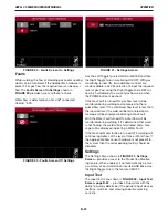
While welding, the flow of shielding gas and/or cooling
water can be monitored if the appropriate hardware is
present. For gas flow, the required level can be speci-
fied. The
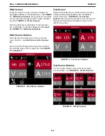
Faults Screen On Settings
shown in
FIGURE 29
provides access to these features.
Water flow is detected by an ArcLink
®
connected
CoolArc
™
55S.
Use the Left Toggle to select GAS or WATER and then
the Right Toggle to turn monitoring ON/OFF. With gas
monitoring turned ON, two additional controls are
made available; a LEVEL selection to input the required
level of gas flow using the Right Toggle and a REF val-
ue which will display the current gas flow value when
the PURGE button is pushed.
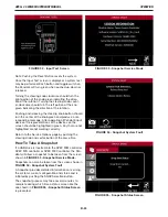
If the Gas Fault is turned ON, gas flow level will be
monitored during welding and compared to the re-
quired flow level. If the monitored flow level is less than
the required level, the weld will be terminated and a
message will be displayed indicating a Gas Fault.
With the Water Fault turned ON, water flow will be
monitored during welding. If it’s determined that water
is not flowing, the weld will be terminated and a mes-
sage will be displayed indicating a Water Fault.
If the Gas and Water faults are turned OFF, welding will
continue regardless of the level of Gas or Water flow. If
the appropriate flow sensor hardware is not present in
the system then the corresponding fault(s) should be
disabled.
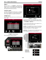
Settings
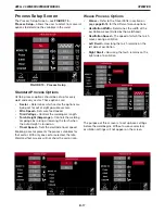
The Settings Menu shown in
FIGURE 31- Settings
Screen –
provides access to the Production Monitor-
ing feature. When enabled, it will automatically archive
a summary of each weld to an inserted USB drive. Use
the Right Toggle to turn this feature ON/OFF.
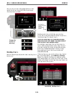
Input Test
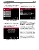
The Input Test menu shown in
FIGURE 32 - Input Test
Screen, page B-24
– provides a Supervisor with the
ability to quickly determine if the pendant input devices
(buttons, switches, and steering knob) are working
correctly.
FIGURE 29 - Faults Screen On Settings
FIGURE 31 - Settings Screen
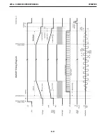
FIGURE 30 - Faults Screen Off Settings

