background image

B-3

OPERATION

SOFTWARE FUNCTIONS

1) Start/Stop Fan feature activated by push button on cabinet

front.

2) Remote Start/Stop Fan feature activated by an external switch

or remote control.

3) Automatic main filter cleaning function triggered in the

following cases:

a) Filter bank offine/online cleaning active immediately,

cleaning is dependent upon fan differential pressure-- the

pressure the filter creates to air flow-- and your set points.

b) Offine cleaning when fan is off.
c) Online cleaning when fan is on.
d) Offine filter pressure cleaning active at three levels of filter

pressure drop (low, medium, high). Each level gradually

increases filter cleaning.

e) Low pressure default value is 400Pa, with a range of

300Pa to 1000Pa. Medium pressure default value is 600Pa,

with a range of 500Pa to 1200Pa. High pressure default

value is 800Pa, with a range of 700Pa to 1400Pa.

f) When the fan is running the filter pressure is monitored.

Once a level is reached, the system will wait for the fan to

shut down before offine cleaning begins. Aside from

hearing air blasts cycling to each filter, the white light will

flash as a visual indication that the unit is cleaning. The

white light will return to steady once the cleaning cycle is

completed. Each valve starting from the top is pulsed with

compressed air. The default pulse time is 250ms. After the

first valve is pulsed, the next one is delayed. This delay is

the valve pulse timer at work, and the default delay time is

15 seconds. The delay allows the air accumulators within

the filter bank to charge.

g) When all the filter have been pulsed, the cleaning cycle has

completed. At the low pressure limit the the cleaning cycle

is 2X. At the medium pressure limit the cleaning cycle is 4X.

And at the high pressure limit the cleaning cycle is 6X. Each

level cleans the filter more aggressively but takes longer to

clean when the cycle is off.

h) If the fan is turned on before the cleaning cycle has

completed offine cleaning will pause. Once the fan is turned

off, filter cleaning will resume at the same sequence it was

stopped at.

i) Online cleaning is activated with the Delta P pressure drop

settings. Default level is 1000Pa with a range of

100Pa-2500Pa. When the fan is running, and the Delta P

level has been reached, the Power On white light will flash

and filter cleaning will start from the top. The same pulse

and pause times from the offline cleaning are used. Online

cleaning will not stop until the filter pressure falls below the

Delta P level.

j) Once the fan is off, offine cleaning will be active.

4) The Delta P Alarm default is set at 1500Pa. When the alarm is

active, the red Alarm light will blink on the main control cabinet.

At this time filter should be ordered from Lincoln Electric.

OPERATION

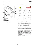
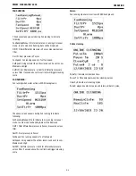
1. FAN RUNNING:

When fan is turned on, PID controller in the PLC will look for Duct

pressure reference and set duct pressure, which can be set to

Low, Medium and High air flow setting using front selector switch.
The default setting of duct pressure based on selection switch 

position:
1. High- 585 pa (501 – 1200)

2. Medium- 331 pa (201 – 500)

3. Low- 147 pa (100 – 200)

2. CLEANING:

When filter pressure exceeds the filter limit pressure, then

ONLINE cleaning is initiated. The filter pressure reading will be

taken once the fan speed stabilized to provide set air flow

delivery.
If user presses the RESET DRIVE ALARM PUSH BUTTON for more 

than 4 seconds, it initiates MANUAL CLEANING process: 
1. Cleaning pulses are generated based on pause time, pulse time

and number cycles.
2. The fan will continue to be ON if online cleaning. It will be

turned OFF if Offline cleaning.

3. PRE-COATED FILTER:

1. The product has function to inhibit cleaning when new filters

installed with pre-coating till the pre-coat hours crossed.
2. There is an hour counter to count the number of hours the fan

run from the date of filter change.
3. The pre-coat hours can be adjusted using PLC display, default

is 0 hours.

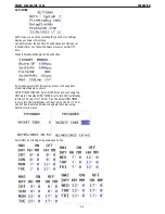
4. DATALOG:

1. The product has function log following data into SD card

mounted on PLC

a) Time stamp
b) Filter pressure
c) Duct pressure
d) % Fan Speed
e) Set point pressure

2. Data log intervals can be adjusted, default set is 30 seconds

(adjustable 10-255 second)

PRISM   

®

CIRCULATOR  4000

®

Summary of Contents for 13232

Page 1: ...or s Manual Need Help Call 1 888 935 3877 to talk to a Service Representative Hours of Operation 8 00 AM to 6 00 PM ET Mon thru Fri After hours Use Ask the Experts at lincolnelectric com A Lincoln Ser...

Page 2: ...A LARGE ROOM OR OUTDOORS natural ventilation may be adequate if you keep your head out of the fumes See below USE NATURAL DRAFTS or fans to keep the fumes away from your face If you develop unusual s...

Page 3: ...belts gears fans and all other moving parts when starting operating or repairing equipment 1 e In some cases it may be necessary to remove safety guards to perform required maintenance Remove guards o...

Page 4: ...to ANSI Z87 I standards 4 b Use suitable clothing made from durable flame resistant material to protect your skin and that of your helpers from the arc rays 4 c Protect other nearby personnel with su...

Page 5: ...nt passing through lifting chains crane cables or other alternate circuits This can create fire hazards or overheat lifting chains or cables until they fail 6 h Also see item 1 c 6 I Read and follow N...

Page 6: ...the arc and filter contaminants out of the air The ventilation or exhaust needed for your application depends upon many factors such as Workspace volume Workspace configuration Number of welders Weld...

Page 7: ...emental Information Not listed Nuisance value maximum is 10 milligrams per cubic meter PEL value for iron oxide is 10 milligrams per cubic meter TLV value for iron oxide is 5 milligrams per cubic mete...

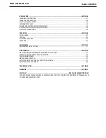
Page 8: ...ON C REPLACEMENT FILTER OPTIONS C 1 MAINTENANCE SECTION D MALFUNCTIONS AND EMERGENCIES EFFECTING THE FILTER UNIT D 1 ESCAPE OF NOXIOUS SUBSTANCES OR RADIATION D 1 PERIODIC MAINTENANCE D 2 MAINTENANCE...

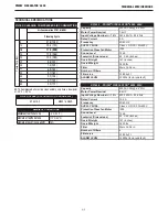
Page 9: ...50 60 HZ SUPPLY FUSE Class J OR CC 15A 600V Protection Class fan Motor IP55 Sound Level 72db Footprint Dimensions 45 X 65 Inches Overall Height 147 inches Overall Weight 1830 lbs Filter Merv 16 Nano N...

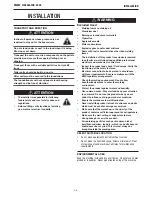
Page 10: ...e safety features Electrical connection to be executed in accordance with local requirements Ensure compliance with the EMC regulatory arrangements Check the working environment Do not allow unauthori...

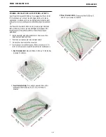
Page 11: ...ust and fume producing areas or placed strategically throughout the guidelines Install circulator along the perimeter of shop away from open doors and exhaust fans Position near input power and compre...

Page 12: ...der Lift Drill The installer is responsible for following federal state and local safety codes and regulations WARNING FALLING EQUIPMENT can cause injury Remove the side access panel as shown Connect...

Page 13: ...e to 5 6 bar 72 87psi Motor cable with the unit is 20ft long Note Check the voltage rating on the yellow Lanyard decal on the Prism Circulator 4000 models have 460V or 230V three phase identify the ap...

Page 14: ...to a power supply grounded according to the National Electrical Code and local codes All electrical wiring which includes primary secondary electrician ELECTROCUTION HAZARD Disconnect mains before ser...

Page 15: ...placement instructions Before opening door unit must be off and the power switch on the side of the control panel turned to the off position FIGURE A 5 FIGURE A 6 FIGURE A 7 FIGURE A 8 Step 6 lock doo...

Page 16: ...zontal vanes in the fan exhaust This can different fan speed Fan Speed Air ow CFM m hr Max Throw Distance m Low 2000 3398 70 21 3 Medium 3000 5097 90 27 4 High 4000 6796 120 36 6 PRISM CIRCULATOR 4000...

Page 17: ...d Solid light indicates that the EC motor drive has faulted C FAN RUNNING Light green indicates the unit is operational and fan is running D RESET DRIVE ALARM Button When RESET DRIVE ALARM PUSH BUTTON...

Page 18: ...off filter cleaning will resume at the same sequence it was stopped at i Online cleaning is activated with the Delta P pressure drop settings Default level is 1000Pa with a range of 100Pa 2500Pa When...

Page 19: ...ustable 100 to 1500 millisecond PulseS2 Adjustable pulse duration for Solenoid 2 default is set to 200 millisecond adjustable 100 to 1500 millisecond PulseS3 Adjustable pulse duration for Solenoid 3 d...

Page 20: ...N RUNNING The above screen appears during Fan running to indicate following FanRunningManual this to indicate fan is running in manual mode In auto mode FanRunning Auto will be displayed FiltrPr Filte...

Page 21: ...y entering password 1234 user can access to change Auto mode time schedule as shown Select HW1 by scrolling using down push button PRISM CIRCULATOR 4000 ON OFF TIME SCHEDULE Auto ON OFF time can be se...

Page 22: ...rtridge MERV 16 high efficiency thermal bonded PTFE KP4519 4 with oil resistant technology MERV 11 spun bond polyester filter cartridge KP4519 5 cartridge with oil resistant technology MERV 16 high ef...

Page 23: ...ry instructions using the plastic sack disposal system supplied Maintenance should only be performed by authorized qualified and trained persons skilled using appropriate work practices When cleaning...

Page 24: ...ose of particulate if necessary Check and log filter pressure Check incoming pressure EVERY 6 MONTHS Ensure that the Cubic Feet per Minute CFM is operating to the engineered specifications based on th...

Page 25: ...may be classified as hazardous waste and will need to be disposed in accordance with federal state and local regulations which could vary from state to state and between local municipalities within th...

Page 26: ...r 2 Unclasp handles to lower lters for removal 1 Install new filters making sure they are pushed against rear of unit 2 Reclasp filter handles to lift filters to their sealed position 3 Re lock door l...

Page 27: ...it into the machine until it stops 2 Lift the handle and allow the left and right latches to rotate inward 3 Release the handle and ensure both latches are engaged with the handle and the handle is lo...

Page 28: ...ific adjustments maintenance or repair jobs which are not dealt with in this manual please contact Lincoln Electric Automation Department 888 935 3878 Make sure you have the following data on hand pro...

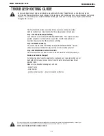
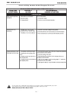
Page 29: ...LECTRIC COM LOCATOR Observe all Safety Guidelines detailed throughout this manual PROBLEMS SYMPTOMS POSSIBLE CAUSE RECOMMENDED COURSE OF ACTION FUNCTION PROBLEMS 1 between control box and tank valves...

Page 30: ...e PLC Fan speed is controlled via this input feeding into a PID control loop 3 If all recommended possible areas of mis adjustment have been checked and the problem persists Contact your local Lincoln...

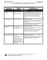
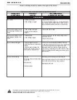
Page 31: ...ke coming out of the inlet opening s Pollution of the facility 1 Outlets blocked 2 Filter cartridge clogged 1 Remove obstructions from the outlet opening s and or connected ductwork 2 Replace filter c...

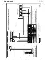
Page 32: ...R REFER EC FAN MOTOR DRIVE SPECIFICATION FOR PROPER INPUT VOLTAGE AND FUSE RATING L3L2L1G 1 2 3 L2 L3 PE 40 NOTES N A COMPONENTS OUT SIDE OF THE CONTROL PANEL ARE INDICATED BY CIRCUIT SURROUNDED BY DO...

Page 33: ...LASS CC 2A 02 02 02 02 120V 240VAC 50Hz 60Hz 1 FUSED DISCONNECT PLC1 14 AWG 14 AWG 2T1 4T2 6T3 PLC easyE4 8IN 4 RELAY O P 14 AWG 24V DC 1N 1L1 0VDC PLC 1 2 3 DC POWER POWER SUPPLY PS1 TB1 TB2 115V 230...

Page 34: ...4 I5 I6 I7 1 INPUT 1 INPUT 2 INPUT 3 INPUT 4 INPUT 5 INPUT 6 FiltPr 0 10VDC 86 OUTPUT Q1 OUTPUT Q2 3 2 4 5 6 INPUT PLC1 OUTPUT 86 SOL1 88 31 OUTPUTQ3 OUTPUT Q4 27 7 8 89 I1 INPUT 7 INPUT8 I8 DuctPr 0...

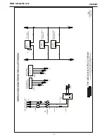
Page 35: ...RIC COMPANYWorld s Leader in Welding and Cutting Products L18498PRINT A 06 Sheet 4 of 5 I2 I3 I4 INPUT 1 INPUT 2 INPUT 3 INPUT 4 RELAY OUTPUTS INPUTS EM1 I1 FILTER CLOG ALARM LAMP LT2 02 50 FAN RUNNIN...

Page 36: ...Cleveland Ohio 44117 1199 U S A THE LINCOLN ELECTRIC COMPANYWorld s Leader in Welding and Cutting Products L18498PRINT A 06 Sheet 5 of 5 ANALOG OUTPUTS ANALOG INPUTS EM2 MOTOR SPEED 0 10V SPEED 0 10V...

Page 37: ...30V COM KL2 2 KL2 2 YELLOW NO KL2 1 KL2 1 RED GND KL3 3 KL3 3 GRAY Din1 KL3 4 KL3 7 BLUE Ain1U KL3 10 KL3 4 PINK Aout KL3 11 KL3 14 GREEN CONNECTION ITEM 6 EC FAN DESC CABLE LEAD YELLOW TB1 88 RED TB1...

Page 38: ...F 7 DIAGRAMS K5140 1 and K5140 2 LAG BOLT MOUNTING DETAILS 36 0 62 5 O 66 4x 43 0 64 0 PRISM CIRCULATOR 4000 65 45 147 95 64 43 101 90...

Page 39: ...This page intentionally left blank...

Page 40: ...This page intentionally left blank...

Page 41: ...This page intentionally left blank...

Page 42: ...parts or electrode with skin or wet clothing l Insulate yourself from work and ground l No toque las partes o los electrodos bajo carga con la piel o ropa moja da l Aislese del trabajo y de la tierra...

Page 43: ...d Entl ftung des Arbeitsplatzes l Mantenha seu rosto da fuma a l Use ventila o e exhaust o para remover fumo da zona respirat ria l Turn power off before servicing l Desconectar el cable de ali mentac...

Page 44: ...or communications Moreover the provision of such information or technical information does not create expand or alter any warranty on our products Any express or implied warranty that might arise fro...

Reviews: