


E-4
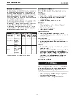
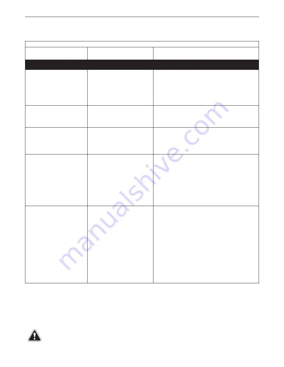
TROUBLESHOOTING
Observe all Safety Guidelines detailed throughout this manual
If for any reason you do not understand the test procedures or are unable to perform the tests/repairs safely, contact your
Lincoln Authorized Service Facility for technical troubleshooting assistance before you proceed.
WWW.LINCOLNELECTRIC.COM/LOCATOR
Observe all Safety Guidelines detailed throughout this manual
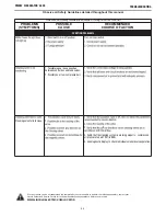
PROBLEMS
(SYMPTOMS)
POSSIBLE
CAUSE
RECOMMENDED
COURSE OF ACTION
FUNCTION PROBLEMS
Poor suction.
1. Outlet(s) are blocked.
2. Filter cartridge is clogged.
1.
Replace
fi
lter if necessary.
2.
If all recommended possible areas of misadjustment have
been checked and the problem persists, Contact your local
Lincoln Authorized Field Service Facility. 1-888-935-3878.
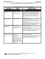
Dust or smoke coming out of the
outlet opening(s). Pollution of the
facility.
1.
Filter cartridge is damaged.
2.
Sealing on
fi
lter cartridge is
damaged.
1. Replace the
fil
ter cartridge.
Dust or smoke coming out of the
inlet opening(s). Pollution of the
facility.
1.
Outlets blocked.
2.
Filter cartridge clogged.
1.
Remove obstructions from the outlet opening(s) and/or
connected ductwork.
2.
Replace
fil
ter cartridge.
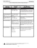
Alarm - Red Alarm LED lights.
1. Red alarm light is on solid if
controls know there is a fault with the
ECM Fan.
2. Red alarm light is flashing if the
filter DP alarm set point is reached
(one second on / one second off).
1. Press alarm reset and investigate ECM Fan fault issue.
2. If the Differential Pressure read by the sensor is higher than
your DP Alarm set point your alarm light will be on and
flashing and the unit most likely has already passed your
online cleaning set point (default of which is 1500 Pa). Filters
need to be changed if this DP reading is correct and your set
point is realistic.
Fan does not start running
No power
No run signal to fan on terminal block
location #51
Motor defective
Controller defective
Determine cause for loss of power at fan and repair.
Check speed signal voltage to fan on terminal block #51 and at
Ain1U in the fan motor housing. Repair as needed.
Repair/Replace fan motor
PRISM
®
CIRCULATOR 4000
®