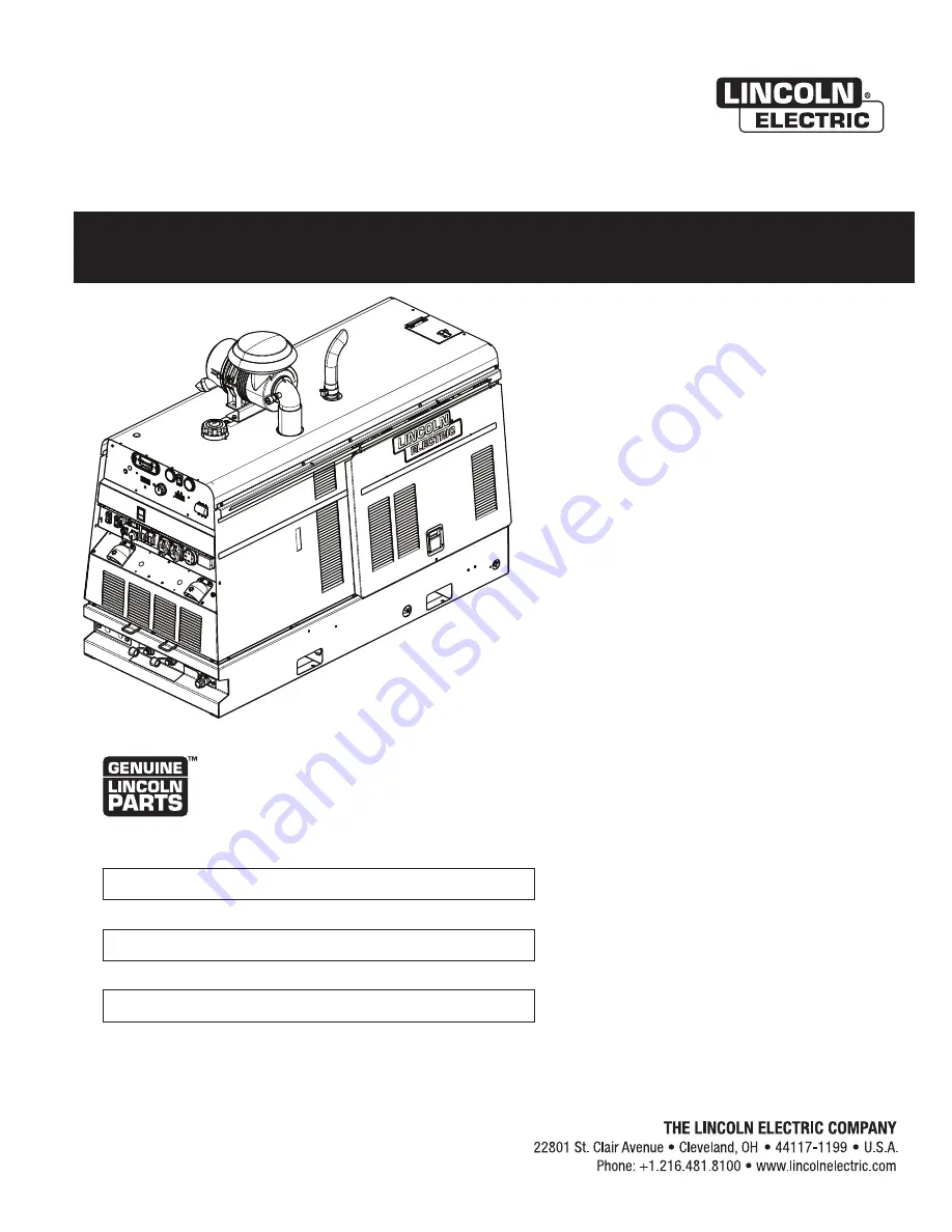
background image

Operator’s Manual

Air Vantage

®

 600X-I

Register your machine:   

www.lincolnelectric.com/register


Authorized Service and Distributor Locator:   

www.lincolnelectric.com/locator


IM10568


  |   Issue D ate Jun - 20 

© Lincoln Global, Inc.  All Rights Reserved.

For use with machines having Code Numbers: 

13057

Need Help? Call 1.888.935.3877  

to talk to a Service Representative


Hours of Operation:  

8:00 AM to 6:00 PM (ET) Mon. thru Fri.


After hours?  

Use “Ask the Experts” at lincolnelectric.com 
A Lincoln Service Representative will contact you  
no later than the following business day.


For Service outside the USA:  

Email: globalservice@lincolnelectric.com

Save for future reference   

Date Purchased 

Code: (ex: 10859) 

Serial: (ex: U1060512345)


Summary of Contents for Air Vantage 600X-I

Page 1: ...machines having Code Numbers 13057 Need Help Call 1 888 935 3877 to talk to a Service Representative Hours of Operation 8 00 AM to 6 00 PM ET Mon thru Fri After hours Use Ask the Experts at lincolnele...

Page 2: ...A LARGE ROOM OR OUTDOORS natural ventilation may be adequate if you keep your head out of the fumes See below USE NATURAL DRAFTS or fans to keep the fumes away from your face If you develop unusual s...

Page 3: ...t engine parts and igniting Do not spill fuel when filling tank If fuel is spilled wipe it up and do not start engine until fumes have been eliminated 1 d Keep all equipment safety guards covers and d...

Page 4: ...m to ANSI Z87 I standards 4 b Use suitable clothing made from durable flame resistant material to protect your skin and that of your helpers from the arc rays 4 c Protect other nearby personnel with s...

Page 5: ...nt passing through lifting chains crane cables or other alternate circuits This can create fire hazards or overheat lifting chains or cables until they fail 6 h Also see item 1 c 6 I Read and follow N...

Page 6: ...T BREAKERS A 6 WELDING OUTPUT CABLES A 8 PULSE WELDING A 8 CABLE INSTALLATION A 8 CABLE INDUCTANCE AND ITS EFFECTS ON WELDING A 9 CONTROL CABLE CONNECTIONS A 9 CROSSLINC TECHNOLOGY A 9 REMOTE CONTROL...

Page 7: ...POWER SOURCES C 2 MAINTENANCE SECTION D ROUTINE AND PERIODIC MAINTENANCE D 1 ENGINE MAINTENANCE D 2 AIR FILTER D 2 FUEL FILTERS D 4 COOLING SYSTEM D 4 CHECKING AND REPLACING COOLANT D 4 BATTERY HANDLI...

Page 8: ...attery Stop Electric Shock Welder Output Auto Idle Fire or explosion Voltage Output High Idle Battery explosion Amperage Output Start Battery acid A Welding Amperage Glow Plug Ur Reduced Open Circuit...

Page 9: ...Glow Plugs Fuel 25 US gal 94 6L Oil 2 25 US gal 8 5L Cooling System 2 5 US gal 9 5L Battery Size BCI Group Size 34 800 Cold Crank Amps RATED OUTPUT 104 F 40 C WELDER Duty Cycle Welding Output Volts a...

Page 10: ...URE A 1 With the VRD switch in the OFF position the VRD lights are non activated LOCATION AND VENTILATION clean cool air to the cooling air inlets and to avoid restricting the cooling air outlets Also...

Page 11: ...equipped with a heavy accessory such as trailer or gas cylinder Do not lift machine if lift bale is damaged Do not operate machine while suspended from lift bale HIGH ALTITUDE OPERATION At higher alti...

Page 12: ...le is stable under conditions of use Do not exceed maximum rated loads for components such as suspension axles and tires Mount equipment base to metal bed or frame of vehicle Do not mount the welder u...

Page 13: ...mp provided secure the outlet pipe to the outlet tube with the pipe positioned such that it will direct the exhaust in the desired direction away from the air intake Tighten using an internal socket o...

Page 14: ...ailed information on testing and resetting the GFCI The auxiliary power of the Air Vantage 600X I consists of the following One 20 amp 120 VAC NEMA 5 20R duplex receptacle with GFCI protection One 50...

Page 15: ...F to install welding cables 2 3 Connect the electrode holder and work cables to the weld front 4 5 Be certain that the metal piece you are welding the work is properly connected to the work clamp and...

Page 16: ...61 m The use of non standard cables especially in lengths greater than 25 feet can lead to communication problems system shutdowns poor motor acceleration poor arc starting and low wire driving force...

Page 17: ...n connector The remote input sets the arc current preset over the full range from minimum to maximum The left digital output display will show the maximum setting for the arc current preset range as s...

Page 18: ...6 The switch positions on the Air Vantage 600X I will be dependent on the type of accessory chosen Reference Table A 4 and Figure A 6 for guidance on how to properly set up each accessory WARNING FIGU...

Page 19: ...Tweco Plug Receptacle 3 0 600A 60 50 ft 15 3 m K2485 3 Adapter Lug to Tweco Style Receptacle Adapter K2487 1 Item Desc K Machine Air Vantage 600X I K4394 2 Remote CrossLinc Remote K4345 1 Weld Power...

Page 20: ...ershield 350A FCAW SS Welding Gun 15 ft 1 16 5 64 K126 12 Work Cable Weld Power Cable Lug to Lug 3 0 600A 60 35 ft 10 6 m K1842 35 Work Clamp GC 500 Work Clamp 500A 60 Duty Cycle K910 2 Weld Power Cab...

Page 21: ...150 10 FIGURE A 9 FIGURE A 10 Item Desc K Machine Air Vantage 600X I K4394 2 Accessory TIG Module K930 2 Control Cable 9 14 Pin Cable K936 1 Torch PTA 26 25 ft K1783 4 Foot Pedal Foot Amptrol 25 ft K8...

Page 22: ...ng door closed and the side panels in place as these provide maximum protection from moving parts and insure proper cooling RECOMMENDED APPLICATIONS WELDER The Air Vantage 600X I provides excellent co...

Page 23: ...position 3 Press START GLOW PLUG switch and hold until machine turns overs 4 Release the engine START GLOW PLUG switch immediately when the engine starts 5 The engine will run at high idle speed for a...

Page 24: ...re fuel level and battery voltage are white They will turn red when outside normal operating ranges 2 DIGITAL OUTPUT METERS The digital meters allow the preset arc output voltage CV WIRE mode or prese...

Page 25: ...of current rise will change when the electrode short circuits to the work Increasing the pinch from 10 to 10 may reduce spatter while 7 WELD MODE SELECTOR SWITCH Provides six selectable welding modes...

Page 26: ...be both lights will illuminate for 5 seconds These lights monitor the OCV and weld voltage at all times When not welding the green light will illuminate indicating that the VRD has reduced the OCV to...

Page 27: ...er the thermal has cleared and closed after the machine has cooled down to an acceptable temperature to reestablish output 32 DIAGNOSTIC PLUG shops to connect and troubleshoot engine error codes found...

Page 28: ...unter clockwise power is cut off from the front panel and is lockable lock not included B 7 39A HOUR METER 39B AMBER FAULT LIGHT 39C COMPRESSOR POWER SWITCH 40 AIR COMPRESSOR OUTLET 39D COMPRESSOR PRE...

Page 29: ...ome on and or the fault light is illuminated turn off the compressor power switch then turn off the machine RUN STOP to OFF and go to the TROUBLE SHOOTING section to locate the cause of the problem 7...

Page 30: ...and stopping compressor rotation 5 The air pressure gage Item 47 indicates that the system is on The pressure at a tool attached to the system will be lower depending on the hose length and restrictio...

Page 31: ...ll show FC SS Figure B 9 FC gS Figure B 10 or MIG Figure B 11 This setting will be stored in system memory and will be remembered between machine power cycles This setting will only be visible if the...

Page 32: ...DEFAULT SETTINGS Pressing and holding the hidden reset push button for 5 seconds will cause certain stored values to be reset to defaults The stored hot start values will return to a default setting o...

Page 33: ...rough the user interface Because of of the following adjustments See ACCESSORIES section for kits and options available to use with the Air Vantage 600X I visit lincolnelectric com or contact your loc...

Page 34: ...ng applications The TOUCH START TIG setting of the MODE switch is for DC TIG to the desired current and the tungsten is touched to the work During the time the tungsten is touching the work there is v...

Page 35: ...3 5 5 10 4 6 9 13 5 6 2 4 3 32 150 250 15 30 6 8 13 17 5 7 11 15 6 7 8 3 2 1 8 250 400 25 40 7 11 15 23 5 7 11 15 4 0 5 32 400 500 40 55 10 12 21 25 6 8 13 17 8 10 4 8 3 16 500 750 55 80 11 13 23 27...

Page 36: ...electrode being used according to the ratings in Table B 3 below If gouging above 450 amps it is recommended to set the machine to HIGH IDLE Maximum current setting is limited to the Air Vantage 600X...

Page 37: ...l stick out while welding Electrical stick out is the distance from the contact tip to the work piece The Air Vantage 600X I waveforms are optimized for a 0 75 stick out The adaptive behavior supports...

Page 38: ...e CrossLinc device will automatically link to the machine The CrossLinc light will be on to show active communication When CrossLinc is active the remote control is disabled CrossLinc technology uses...

Page 39: ...current is being drawn The auxiliary power of the Air Vantage 600X I consists of the following One 20 amp 120 VAC NEMA 5 20R duplex receptacle with GFCI protection The auxiliary power capacity is 7 8...

Page 40: ...utz TD2 9L4 Fuel Consumption Full Tank equals 25 gal 94 6L GAL HR L HR RUN TIME HRS WITH FULL TANK High Idle 0 79 3 01 31 5 Low Idle 0 59 2 24 42 4 100A 24V 0 91 3 44 27 5 200A 28V 1 05 3 98 23 8 300A...

Page 41: ...justment knob sets the low end setpoint for increased resolution Remote comes standard with a 6 pin plug 12 pin to 6 pin Adaptor K2909 1 needed Optional built in 120 VAC receptacles available Order K4...

Page 42: ...ides smooth and stable AC TIG welding on aluminum and DC TIG welding on steel stainless steel and chrome moly Order K5126 1 PowerMIG 210MP The push and turn digital controls and color display screen m...

Page 43: ...ng parts troubleshooting work ROUTINE AND PERIODIC MAINTENANCE DAILY Check the engine oil level tank Open the water drain valve located on the bottom of the water separator element 1 or 2 turns and al...

Page 44: ...the air cleaner Rapid engine wear will result from contaminants such as dust and dirt being drawn into the engine apply oil to it Service the air cleaner per instructions on page D 3 WARNING AIR VANT...

Page 45: ...the entire air cleaner system are tight Check for holes in piping and repair if needed Any leaks in your intake piping will send dust directly to the engine The critical sealing area will stretch slig...

Page 46: ...or Fill up to the To drain the coolant open the valve at the bottom of the radiator Open the radiator cap to allow complete drainage Tighten the automotive grade low silicate ethylene glycol antifreez...

Page 47: ...ternal charger discon attach the charger leads After the battery is charged reconnect to do so can result in damage to the internal charger components Follow the instructions of the battery charger ma...

Page 48: ...rements please refer to the Engine Owner s Manual NAMEPLATES WARNING DECALS MAINTENANCE Whenever routine maintenance is performed on this machine or at least yearly inspect all nameplates and labels f...

Page 49: ...ppliance connected to it but trips each time an appliance is connected to it the appliance has a ground fault and needs to be repaired or replaced DO NOT USE THE APPLIANCE IF THIS CONDITION OCCURS A R...

Page 50: ...oughout this manual This Troubleshooting Guide is provided to help you locate and repair possible machine malfunctions Simply follow the three step procedure listed below Step 1 LOCATE PROBLEM SYMPTOM...

Page 51: ...contact your Field Service Facility 6 Check 30A Breaker ECU 1 Out of fuel 2 Fuel shut off valve is in the off posi tion make sure the valve lever is in the open position lever in line with the Hose 3...

Page 52: ...ery 2 Faulty engine alternator 3 Loose or broken lead in charging circuit 4 Loose fan belt may need tighten ing 1 Idler switch in HIGH idle position make sure switch is set to AUTO 2 Faulty relay 3 Fa...

Page 53: ...ld Control PCB or Idler relay 1 Broken lead in rotor circuit 3 Faulty Weld Control PCB 4 Faulty rotor 1 Faulty remote kit 2 Faulty output control poten tiometer 3 Faulty output control wiring 4 Faulty...

Page 54: ...87 62 PIN ENGINE CONNECTOR 60 PIN ECU A CONNECTOR 94 PIN ECU B CONNECTOR GLOW IDLE FUEL 405B ECB54B 261 5P 5M 5M 5N 1 2 3 1 2 1 5 2 3 6 8 7 232A 236A 5S 256A 257 232 236A ECB88 57 64 13 87 29 15 68 44...

Page 55: ...03 1 32 93 836 3 45 59 1157 9 3 82 97 1 8 95 227 3 28 99 736 2 19 63 498 6 23 96 608 6 50 38 1279 6 54 44 1382 9 7 03 178 5 24 47 621 4 12 61 320 3 20 69 525 5 43 36 1101 2 51 44 1306 5 69 00 1752 6 5...

Page 56: ...tomer s particular purpose with respect to such information or advice As a matter of practical consideration we also cannot assume any respon sibility for updating or correcting any such information o...

Reviews: