background image

FineLine 300HD Plasma System 

BK8053-000107 Rev A.01 

This information is subject to the controls of the Export Administration Regulations [EAR]. This information shall not be provided to 

non-U.S. persons or transferred by any means to any location outside the United States contrary to the requirements of the EAR. 

Page 110 of 118 

9.2 Cooling System (Inside Power Supply) Flow Diagram 


Summary of Contents for FineLine 12864

Page 1: ...oln Global Inc All Rights Reserved For use with machines having Code Numbers 12864 Save for future reference Date Purchased Code ex 10859 Serial ex U1060512345 This information is subject to the controls of the Export Administration Regulations EAR This information shall not be provided to non U S persons or transferred by any means to any location outside the United States contrary to the require...

Page 2: ...and to exceed their expectations On occasion purchasers may ask Lincoln Electric for advice or information about their use of our products We respond to our customers based on the best information in our possession at that time Lincoln Electric is not in a position to warrant or guarantee such advice and assumes no liability with respect to such information or advice We expressly disclaim any warr...

Page 3: ...ng System and Torch Coolant 14 2 6 Gas Supply 15 2 7 FineLine Automatic Gas Console AGC 16 2 8 FineLine Arc Start Console ASC 17 2 9 Magnum PRO LC300M Plasma Torch 18 2 10 FineLine Plasma Console App CutLinc Server 19 2 11 Ethernet Router Switch 19 2 12 Airborne Noise Emissions 20 2 13 Electromagnetic Compatibility EMC 20 3 0 Installation 21 3 1 Component Placement 21 3 2 Connection Diagram 25 3 3...

Page 4: ... 5 6 Replacing Consumables 67 5 7 Cutting Charts 69 6 0 Maintenance 75 6 1 Routine Maintenance 76 6 2 Coolant Filter Replacement without coolant flush 78 6 3 Coolant Flush and Filter Replacement 79 6 4 Consumable Inspection 81 6 5 Software Firmware Updates 82 7 0 Troubleshooting 85 7 1 Error Code Identification 85 7 2 Error Codes 86 8 0 Parts List 91 8 1 FineLine 300HD Power Supply KP4900 1 91 8 2...

Page 5: ... WARNING Cancer and Reproductive Harm www P65warnings ca gov 1 3 Ultraviolet Radiation Protection Plasma cutting produces ultraviolet radiation similar to a welding arc This ultraviolet radiation can cause skin and eye burns For this reason it is essential that proper protection be worn The eyes are best protected by using safety glasses or a welding helmet with an AWS No 12 shade or ISO 4850 No 1...

Page 6: ...nts should be removed from the area prior to cutting Galvanized metal can produce harmful gases during the cutting process Ensure proper ventilation and use breathing equipment when cutting these materials Certain metals coated with or containing lead cadmium zinc beryllium and mercury produce harmful toxins Do not cut these metals unless all people subjected to the fumes wear proper air breathing...

Page 7: ... the input power ground stud on the Power Supply Make sure the connection is securely tightened Make sure the positive output work ground of the Power Supply is connected to a bare metal area on the cutting table A driven ground rod should be placed no further than five feet from this connection Make sure this ground point on the cutting table is used as the star ground point for all other ground ...

Page 8: ...by the U S Compressed Gas Association CGA American Welding Society AWS Canadian Standards Association CSA or other local or national codes Compressed gas cylinders should be maintained properly Never attempt to use a cylinder that is leaking cracked or has other signs of physical damage All gas cylinders should be secured to a wall or rack to prevent accidental knock over If a compressed gas cylin...

Page 9: ...cesses obtainable from the American Welding Society 550 NW LeJeune Road Miami FL 33126 ANSI Standard Z41 1 Standard For Men s Safety Toe Footwear obtainable from the American National Standards Institute 11 West 42nd Street New York NY 10036 ANSI Standard Z49 2 Fire Prevention in the Use of Cutting and Welding Processes obtainable from the American National Standards Institute 11 West 42nd Street ...

Page 10: ...s obtainable from the Compressed Gas Association 1725 Jefferson Davis Highway Suite 1004 Arlington VA 22202 CGA booklet TB 3 Hose Line Flashback Arrestors obtainable from the Compressed Gas Association 1725 Jefferson Davis Highway Suite 1004 Arlington VA 22202 CSA Standard W117 2 Safety in Welding Cutting and Allied Processes obtainable from Canadian Standards Association 178 Rexdale Boulevard Tor...

Page 11: ...ble of producing 300A output current at a 100 duty cycle It is capable of piercing mild steel up to 1 75 in 45mm and severance cutting up to 3 in 75mm It is also capable of plasma marking which creates a noticeable mark in the metal surface without cutting through the metal 2 2 System Components 2 2 1 Standard Components FineLine 300HD Power Supply K4900 1 FineLine Automatic Gas Console AGC BK3003...

Page 12: ... of the EAR Page 12 of 118 2 2 2 Supplied Optionally Oxygen Supply Gas Hose BK200362 XX H17 Supply Gas Hose BK200363 XX Air Supply Gas Hose BK200364 XX Nitrogen or Argon Supply Gas Hose BK200365 XX Supply Gas Hose Fittings Kit BK300421 CNC Interface Cable BK602610 XX Human Machine Interface CNC Controller 2 2 3 Supplied by OEM or End User Human Machine Interface CNC Controller or Industrial Comput...

Page 13: ... Supply K4900 1 Input Voltage and Current Duty Cycle 100 Input Voltage 10 380 415 460 575 Input Amperes 122 107 93 Idle Power W 225 Power Factor 0 95 K4900 1 Rated Output at 40 C Duty Cycle 100 Current 300 A Voltage 210 V K4900 1 Output Current Range 20 300 Amps Open Circuit Voltage 300 VDC Pilot Current 30 Amps Temperature and Environment Operating Temperature 14 F to 104 F 10 C to 40 C Storage T...

Page 14: ...ection down to 9º F 13º C Torch coolant can be ordered in 1 0 gallon 3 8 liter containers part number BK500695 DO NOT USE automotive or other commercial anti freeze that contains rust inhibitors or leak stoppers These coolants will damage the pump and block the small internal passageways in the heat exchanger affecting cooling performance To avoid freeze damage and fluid leakage during shipment th...

Page 15: ...145 psi 10 0 bar Oxygen and nitrogen should be supplied with a purity of at least 99 5 H17 purity should be at least 99 995 Argon purity should be at least 99 99 All should be clean dry and oil free A potential fire hazard exists when cutting with oxygen It is recommended that an exhaust ventilation system be used when cutting with oxygen Flashback arrestors must be supplied unless they are not av...

Page 16: ...vided to non U S persons or transferred by any means to any location outside the United States contrary to the requirements of the EAR Page 16 of 118 2 7 FineLine Automatic Gas Console AGC Part Number BK300350 Weight 15 7 lbs 7 12 kg Physical Dimensions and Mounting 6 51 165mm 7 30 185mm 11 08 281mm 2 70 69mm 4 56 116mm 4 56 116mm Ø 0 28 7 1mm 3 MOUNTING HOLES FOR M6 BOLTS ...

Page 17: ... be provided to non U S persons or transferred by any means to any location outside the United States contrary to the requirements of the EAR Page 17 of 118 2 8 FineLine Arc Start Console ASC Part Number K4901 1 Weight 18 9 lbs 8 57 kg Physical Dimensions and Mounting Ø 0 31 7 9mm 4 MOUNTING HOLES FOR M6 BOLTS 12 77 324mm 10 98 279mm 13 52 343mm 8 00 203mm 5 29 134mm ...

Page 18: ...0 95 kg Torch Handle Part Number BK602621 Torch Handle Weight 0 95 lbs 0 43 kg Torch Clamp Part Number BK700223 Torch Clamp Weight 0 75 lbs 0 34 kg Minimum Gas Pressure at Torch 5 psi 0 4 bar Maximum Gas Pressure at Torch 95 psi 6 6 bar Torch Arc Strike Voltage Rating 7 5kV Physical Dimensions and Mounting Torch Clamp Mounting Surface Ø 1 50 38mm Ø 1 99 51mm Torch Handle 5 45 138mm Torch 7 38 187m...

Page 19: ...ing the FineLine Plasma Console App and CutLinc Server The Fineline Plasma Console App is the user interface for the FineLine Plasma System CutLinc Server is the communication hub for the FineLine Plasma System They are already integrated into certain Lincoln Electric HMIs Other HMIs require both to be integrated by the OEM or end user Specifications for the HMI Windows 10 operating system One 1 E...

Page 20: ...ion should be used as defined by local or national codes The following chart gives the noise levels generated by the System when operating at 300 amps 180 arc volts The measurements were made with a sound level meter Distance From Torch A Weighted Sound Pressure Level C Weighted Sound Pressure Level 1 meter horizontal 1 6 meters above the workpiece 108 dB 106 dB The maximum noise level is 126 dB a...

Page 21: ...ation deceleration WARNING Falling equipment can cause injury Lift only with equipment of adequate lifting capacity Be sure Power Supply is stable when lifting The proper location of the Power Supply will provide dependable service and reduce periodic maintenance time Choose a location that will provide unrestricted air movement into and out of the Power Supply Maintain at least 24 in 609 6mm of s...

Page 22: ...ated The plasma and shield hoses connecting the torch to the AGC run inside the torch leads for 6 ft 1 83m before breaking out to connect to the AGC As such the AGC has to be mounted within 2 ft 0 61m of the torch lead routing To minimize high frequency interference from the arc starting circuit it is recommended that the AGC be mounted as far as possible 2 ft 0 61m from the torch leads with the c...

Page 23: ... may interfere with the operation of sensitive control electronics The ASC is usually mounted on the gantry of the cutting machine or on the cutting table The ASC is IP23 rated Secure the ASC to the mounting surface using four or M6 bolts Refer to the mounting pattern shown in Section 2 8 3 1 4 Torch The torch should be installed on the positioner of a height control system capable of maintaining ...

Page 24: ...on is subject to the controls of the Export Administration Regulations EAR This information shall not be provided to non U S persons or transferred by any means to any location outside the United States contrary to the requirements of the EAR Page 24 of 118 BLANK PAGE ...

Page 25: ...m Figure 1 FineLine 300HD System Connection Diagram Ethernet Router Switch Plasma Console App AGC Input Side AGC Output Side ASC Input Side ASC Output Side Torch Power Supply Supply Gas Hoses Nitrogen Oxygen H17 Argon Air Star Ground Plasma Hose Shield Hose Torch Leads ASC Control Cable PS Nozzle Lead PS Electrode Lead Coolant Return Hose Coolant Supply Hose PS Interconnect Cable Ethernet Cable Et...

Page 26: ...he plasma and all other system components such as drive amplifiers and CNC The PE or Service ground must be connected to each piece of equipment per local and national codes DC power ground This is the work lead of the Power Supply and is connected to the cutting table to complete the electrical path for the cutting current RF EMI ground This is the ground for limiting RF EMI noise in the System T...

Page 27: ...e ground connection to the star ground point even if bolted to the gantry or Power Supply Grounds are not to be daisy chained For components mounted to the cutting table gantry it is acceptable to create a star ground at the gantry with a single ground cable connecting the gantry star ground with the cutting table star ground Refer to Appendix A for additional information Star GND Cutting Table Wo...

Page 28: ...3 50 60 122 150 1 0 70 6 16 460V 3 50 60 107 125 1 50 6 16 575V 3 50 60 93 100 2 35 8 10 1 Wire and Fuse Sizes based upon the U S National Electric Code and maximum output 2 Also called inverse time or thermal magnetic circuit breakers circuit breakers that have a delay in tripping action that decreases as the magnitude of the current increases Connection to the supply circuit can be by means of f...

Page 29: ...s EAR This information shall not be provided to non U S persons or transferred by any means to any location outside the United States contrary to the requirements of the EAR Page 29 of 118 Figure 2 Primary Power Connections Route through Strain Relief Disconnect Box U V W 380 415V 460V 575V Access Panel Removed Voltage Selection Jumper ...

Page 30: ...nnections Make connections in the order shown below When making brass fitting connections use two opposing wrenches and only tighten enough to make gas seals The fittings are subject to damage if over tightened Argon Inlet Argon is optional and provides improved marking capabilities If not used this inlet should be capped Nitrogen Inlet Nitrogen must be supplied for cutting stainless steel and alu...

Page 31: ...ear of the Power Supply and connect it with the provided hardware to the terminal labelled with the symbol shown 4 Connect the other end of the work ground lead to the star ground point for the cutting system Make sure that good metal to metal contact is made Power Supply Nozzle Lead 5 Route the 1 2 lug of the Power Supply nozzle lead through the opening in the rear of the Power Supply and connect...

Page 32: ...s information shall not be provided to non U S persons or transferred by any means to any location outside the United States contrary to the requirements of the EAR Page 32 of 118 Figure 4 Power Supply Output Connections To Star Ground To ASC To ASC P1 Route through opening Access Panel Removed To AGC Circuit Breaker for P1 Connector 24VDC 3 5A ...

Page 33: ...istration Regulations EAR This information shall not be provided to non U S persons or transferred by any means to any location outside the United States contrary to the requirements of the EAR Page 33 of 118 Figure 5 Power Supply Output Connections From Power Supply P1 From Power Supply Route through Strain Relief ...

Page 34: ...raided shield to the ASC enclosure in order to help reduce high frequency noise emission Using an ohmmeter measure for zero ohms between the braided shield and the ground stud located on the outside of the ASC enclosure 3 Connect the torch CTP Clear The Plate a k a Ohmic Sense sensor lead to the red hexagonal standoff 4 Connect the torch electrode coolant supply lead to the brass cathode manifold ...

Page 35: ...nformation shall not be provided to non U S persons or transferred by any means to any location outside the United States contrary to the requirements of the EAR Page 35 of 118 Figure 6 ASC Output Connections From ASC P2 To AGC Torch Leads To Star Ground Torch Electrode Coolant Supply Torch Nozzle Lead P2 Torch CTP Sensor Lead Torch Coolant Return ...

Page 36: ...ower Supply Plasma Marking Gas Hose 2 Connect the plasma marking hose to the fitting on the input side of the AGC labelled with the symbol shown and to the corresponding fitting on the Power Supply Shield Marking Gas Hose 3 Connect the shield marking hose to the fitting on the input side of the AGC labelled with the symbol shown and to the corresponding fitting on the Power Supply Shield Cutting G...

Page 37: ...f the Export Administration Regulations EAR This information shall not be provided to non U S persons or transferred by any means to any location outside the United States contrary to the requirements of the EAR Page 37 of 118 Figure 7 AGC Input Connections From Power Supply To Star Ground From AGC ...

Page 38: ...tomatic Gas Console Output Connections Refer to Figure 8 for the physical location of all connections Plasma Hose 1 Connect the plasma hose which exits from the torch leads about 6 ft 1 83m from the torch end to the fitting on the output side of the AGC labelled with the symbol shown Shield Hose 2 Connect the shield hose which exits from the torch leads about 6 ft 1 83m from the torch end to the f...

Page 39: ...Make sure that all fittings are visible so that connections can be made Electrode Coolant Supply Lead 2 Connect the electrode coolant supply lead to the corresponding fitting on the torch Plasma Gas Hose 3 Connect the plasma gas hose to the corresponding fitting on the torch Nozzle Lead 4 Connect the nozzle lead to the corresponding fitting on the torch Shield Gas Hose 5 Connect the shield gas hos...

Page 40: ...ure with the two provided set screws using a 3 32 2 5mm hex key Torch Clamp 3 Separate the two halves of the torch clamp by removing the two socket head cap screws 8 32 x 1 using a 9 64 3 5mm hex key Refer to Section 2 9 for the mounting pattern which requires three 3 user supplied 10 32 socket head cap screws Mount the torch clamp base to the mounting surface so that the torch is positioned 90 de...

Page 41: ...roblems poor cut quality and short consumable life Remove primary wall power from the System Apply lubricant BK716012 to the o ring on the electrode Push the electrode over the cooling tube and thread the electrode into the torch by hand Tighten the electrode using a 10mm 6 point deep socket part number BK602396 and driver part number BK277086 Apply lubricant to the o rings on the swirl ring Press...

Page 42: ...lete Power Supply to Ethernet Router Switch 1 Route the bayonet connector end of an Ethernet cable through the opening in the rear of the Power Supply Plug it into the connector labelled with the symbol shown Connect the other end to the Ethernet router switch AGC to Ethernet Router Switch 2 Connect the bayonet connector end of an Ethernet cable to the connector on the AGC labelled with the symbol...

Page 43: ...top is engaged The OEM or end user must supply the EStop enable disable switches and wiring The Safety Relay employs dual monitored EStop input circuits Both are required and must be isolated from each other for proper operation Switch contacts must be rated for 35 VDC 100mA Refer to Figure 12 for the physical location of all connections Replace the access panel on the Power Supply when installati...

Page 44: ... 3 15 CNC Interface The AGC provides an optional CNC interface P6 for legacy products and robotic applications The following I O is provided Start Input 24Vdc 20ma o Pin 1 Pin 2 Transferred Arc Output 24Vdc 20mA o Pin 3 Pin 4 Plate Sense Output 24Vdc 20mA o Pin 5 Pin 6 o opens upon sensing plate by default o logic can be inverted Arc Voltage Output o Pin 7 Pin 8 o Arc voltage is represented as a c...

Page 45: ...er run file C Program Files Lincoln Electric CutLincServer startCLServer bat Discovery for Single Torch Systems When any of the System s Ethernet adapters are replaced e g Processor Engine PCB in the AGC the CutLinc server needs to be updated with the new MAC address To have the CutLinc server automatically discover the new MAC address delete the following file and then reboot the HMI C local User...

Page 46: ... the EAR Page 46 of 118 3 Select Internet Protocol Version 4 TCP Ipv4 and then the Alternate Configuration tab In the User configured section enter the IP address and Subnet mask shown below 3 16 2 Plasma Console App Installation If the System uses a non Lincoln Electric HMI CNC Controller or Industrial Computer the Plasma Console App must be installed Installation of the Plasma Console App is not...

Page 47: ... top of the Power Supply Pour 4 5 gallons 15 18 liters of approved torch coolant through a funnel and into the coolant reservoir The full level is the bottom of the reservoir neck Wipe up any spilled coolant Replace the reservoir cap Ensure the torch and consumables are properly installed Apply primary wall power and then start the HMI and Plasma Console App Clear the EStop if installed Press the ...

Page 48: ...erly grounded according to local and national codes Primary power is connected to the System according to local and national codes The voltage selection jumper matches the supplied voltage Refer to Section 3 4 Gasses are connected properly Fittings have been checked for leaks All System components are connected properly Refer to Section 3 2 Torch assembly is securely mounted and consumables are in...

Page 49: ...o errors faults Blinking Red Error Record error code and refer to Section 7 0 for troubleshooting Off not lit Off Primary wall power removed Temperature Steady Red Thermal fault Refer to Section 7 0 for troubleshooting Off not lit Internal temperature is OK DC Power Steady Red Output voltage current currently being supplied Off not lit No output of voltage current being supplied ON Button Pulsing ...

Page 50: ...utton Grey Not ready System outputs are disabled Press to enter ready state Grey no icon System outputs are being enabled This may take up to 8 seconds Button has no function during this time Green Ready Waiting for start signal System outputs are enabled Press to enter not ready state 4 1 3 AGC Icon Name Color Description Status Blinking Green 1 per second Normal AGC has power Ethernet connected ...

Page 51: ...ation The System ON button Plasma Console App will be grey 4 2 2 Make a Cut or Mark Select the Material Type Thickness and Process on the Plasma Console App Refer to Section 4 3 Note that gases will purge automatically when switching between oxidizing gas or oxygen containing gas to combustible gas and vice versa Select View Torch Parts on the Plasma Console App Identify which consumables are requ...

Page 52: ... circuit is de energized f Transferred arc is established and the pilot arc is turned off g Motion signal is sent from the System to the CNC h Power supply initiates current upslope to the selected current level Initiate a stop signal via the CNC which will trigger the following sequence a Power supply initiates current downslope b Transferred arc is extinguished the DC Power light is extinguished...

Page 53: ...user interface for the entire System It runs on the HMI which can be a CNC Controller or Industrial Computer Screen Navigation and System ON Button Press the navigation buttons along the bottom of the screen to access all the settings and parameters described in this section Screen Navigation Buttons Press to access the desired screen System ON Button Refer to Section 4 1 2 Important Icons Icons a...

Page 54: ...indow displays various conditions errors and notifications as well as description of the issue All codes are recorded in the error log Diagnostics Error Log Refer to Section 7 0 for troubleshooting Common Examples Action Required Alert Error and Icon The System has encountered an error and is displaying an alert Investigate and resolve the error and then press OK to acknowledge the message Notific...

Page 55: ...ose selections to automatically set the Current Amps Gas Types and Pressures Select the Material Type Press the Material Type button and then select the material to be processed Select the Material Thickness Press the Thickness button and then select the thickness of the material to be processed Or press the data entry button to manually enter the material s thickness Select the Process Press to s...

Page 56: ...e application or operator s experience Changes to Material Type Thickness or Process will automatically reset Current Amps Gas Types and Pressures to default values based upon the cutting charts See Current Lock for the exception Current Amps Press the Current button and then select from the list of amperages Current Lock Press the icon to lock the Current Amps so changes to Material Type or Thick...

Page 57: ...le are displayed for reference Use this information to build up the torch with the necessary consumables Refer to Section 5 6 for the complete procedure Press Cancel to return to the Material screen 4 3 6 Confirm Cutting Marking Parameters Press the Parameters button to confirm the cutting and marking parameters The default values are determined by the active selections on the Material screen Pres...

Page 58: ...will display the time remaining A message at the top of the screen indicates when the AGC is Purging Gases and the background color will be yellow NOTE The system does not regulate actual pressures to the set point pressures during a purge they are regulated to 80 psi during a purge 4 3 8 Make a Cut or Mark Follow the sequence in Section 4 2 to make a cut or mark with the System 4 3 9 Moving Pierc...

Page 59: ...p Diagnostics 4 4 1 Diagnostics Pressures Coolant Tab Press the Diagnostics button followed by the Pressures Coolant tab to access the screen and settings described below Input Pressure The values displayed are measured at the Power Supply Coolant Press the Fill Flush button to circulate coolant through the System during the initial filling or during maintenance Press the button again to stop circ...

Page 60: ...the United States contrary to the requirements of the EAR Page 60 of 118 4 4 3 Diagnostics Electrical Tab Press the Diagnostics button followed by the Electrical tab to access the screen described below This screen displays the Automatic Gas Console and Power Supply electrical parameters 4 4 4 Diagnostics Cut Info Tab Press the Diagnostics button followed by the Cut Info tab to access the screen d...

Page 61: ...the requirements of the EAR Page 61 of 118 4 4 5 Diagnostics Error Log Tab Press the Diagnostics button followed by the Error Log tab to access the screen described below Filters along the right side of the screen can be used to limit the data displayed based upon Error or Date Press the Clear button to remove all filters 4 4 6 Diagnostics Misc Press the Diagnostics button followed by the Misc tab...

Page 62: ... Regulations EAR This information shall not be provided to non U S persons or transferred by any means to any location outside the United States contrary to the requirements of the EAR Page 62 of 118 4 4 7 Diagnostics Versions Tab Press the Diagnostics button followed by the Versions tab to access the screen described below ...

Page 63: ... and when the arc is extinguished During this time the gases and cutting current are changed to optimum values for extinguishing the arc Ideally the CNC controller should provide a plasma stop signal prior to the end of the cut path so the gases and current reach the shut off values at the same time that the part has been completely cut The shutdown times are different for each current and are giv...

Page 64: ...to cut a given plate thickness A negative cut angle top dimension of piece larger than the bottom dimension usually occurs when the torch standoff distance is too low or when the cutting speed is too slow Top dross usually occurs when the torch standoff distance is too high Bottom dross usually occurs when the cutting speed is either too slow slow speed dross or too fast high speed dross Low speed...

Page 65: ... to the cutting height and come into contact with this solidified metal The torch should not move from the pierce height down to the cutting height until the CNC controller has moved the torch away from the pierce point One way to accomplish this may be to program the pierce time on the torch height control system to a value that is longer than the CNC controller motion delay time 5 4 Moving Pierc...

Page 66: ...of 118 5 5 Selecting Consumables Mild Steel Oxygen Plasma Air Shield Outer Cap Shield Cap Retaining Cap Nozzle Swirl Ring Electrode Torch BK602365 BK602340 BK602338 BK602312 BK602354 BK602300 BK602622 30A BK602365 BK602342 BK602338 BK602314 BK602356 BK602301 BK602622 80A BK602365 BK602343 BK602339 BK602315 BK602358 BK602309 BK602622 140A BK602365 BK602345 BK602332 BK602317 BK602359 BK602304 BK6026...

Page 67: ...l the shield cap off of the retaining cap or remove it from the outer cap Unscrew the retaining cap from the torch Pull the nozzle straight out of the torch The swirl ring will come out with the nozzle Do not use tools Separate the swirl ring and nozzle by pulling them apart Do not use tools Unscrew the electrode from the torch using a 10mm 6 point deep socket part number BK602396 and driver part ...

Page 68: ...d the retaining cap onto the torch until it is fully seated Apply lubricant to the o ring on the shield cap Push the shield cap onto the retaining cap until it is fully seated or push the shield cap into the outer cap until it is fully seated Apply lubricant to the o rings on the torch Thread the outer retaining cap onto the torch until it is fully seated Apply primary wall power to the System End...

Page 69: ...nded to give the operator the best starting point to use when making a cut on a particular material type and thickness Small adjustments may have to be made to achieve the best cut Also remember that the arc voltage must be increased as the electrode wears in order to maintain the correct cutting height Cutting Chart Index Material Grade Current Plasma Gas Shield Gas Page Reference Mild Steel A36 ...

Page 70: ...ting Height in Pierce Height in Pierce Time msec Kerf Width in 24 GA 38 82 9 82 116 150 0 090 0 100 100 0 056 22 GA 120 125 0 105 0 120 20 GA 105 0 058 18 GA 100 0 125 0 130 0 062 16 GA 126 75 0 140 0 150 200 0 064 14 GA 128 65 0 145 0 066 12 GA 131 55 300 0 077 10 GA 133 40 0 160 0 160 400 0 085 3 16 141 30 0 200 0 200 700 0 095 Metric Material Thickness mm Preflow psi Plasma psi Shield psi Postf...

Page 71: ... psi Plasma psi Shield psi Postflow psi Arc Voltage volts Travel Speed ipm Cutting Height in Pierce Height in Pierce Time msec Kerf Width in 10 Ga 21 75 14 75 112 180 0 080 0 200 300 0 078 3 16 108 155 0 070 1 4 112 110 0 100 400 0 073 5 16 115 96 0 225 500 0 077 3 8 117 75 0 250 600 0 080 1 2 12 118 50 0 275 900 Metric Material Thickness mm Preflow psi Plasma psi Shield psi Postflow psi Arc Volta...

Page 72: ...0 0 105 0 200 300 0 088 3 16 122 205 400 0 090 1 4 160 0 225 500 5 16 124 140 0 250 600 0 092 3 8 55 120 0 275 0 094 1 2 128 86 0 300 700 0 103 5 8 133 70 0 140 0 325 900 0 105 3 4 136 55 0 350 1100 0 110 1 00 45 142 35 0 160 0 400 1600 0 120 1 25 152 20 0 200 1500 0 135 1 50 36 162 12 0 225 0 158 Metric Material Thickness mm Preflow psi Plasma psi Shield psi Postflow psi Arc Voltage volts Travel ...

Page 73: ...30 0 080 0 250 300 0 100 3 8 131 145 0 100 400 0 114 1 2 135 120 0 115 0 300 500 0 117 5 8 138 100 0 130 0 350 600 0 118 3 4 52 142 75 0 150 0 400 800 0 125 1 143 50 0 175 0 450 1100 0 136 1 25 155 30 0 200 0 500 1800 0 150 1 5 165 20 0 275 0 350 1500 0 188 1 75 43 176 14 0 325 0 205 2 188 7 0 350 0 222 Metric Material Thickness mm Preflow psi Plasma psi Shield psi Postflow psi Arc Voltage volts T...

Page 74: ... 5 8 56 56 130 115 900 3 4 131 90 1000 7 8 49 132 80 0 425 1200 1 133 70 0 450 1300 0 142 1 25 140 50 0 175 0 650 1800 0 160 1 5 145 37 0 200 0 750 2500 0 170 1 75 150 30 0 250 0 850 3200 0 190 2 158 21 0 275 0 450 1500 0 205 2 25 44 163 16 0 300 0 217 2 5 35 168 12 0 325 0 240 2 75 174 8 0 245 3 180 6 0 254 Metric Material Thickness mm Preflow psi Plasma psi Shield psi Postflow psi Arc Voltage vo...

Page 75: ...hair clothing and tools away from the fans inside the cooling system WARNING Capacitor failure can injure and or cause property damage Large electrolytic capacitors store large amounts of energy even after power has been removed from the System Wait at least five minutes after turning off power and then use a voltmeter to verify that the capacitors are fully discharged before performing System mai...

Page 76: ...ctors are installed securely Verify all rear cable connectors are installed securely Verify the electrode lead and work ground lead are secure and free from corrosion Verify that all gas hose connectors are tight and that there are no leaks Only tighten the fittings enough to make water or gas seals The fittings are subject to damage if over tightened Check the torch coolant filter cartridge and r...

Page 77: ...tart console enclosure Inspect the braided shield for nicks or cuts and replace if necessary Remove the torch handle and verify that the connections at the torch are tightened securely Only tighten the fittings enough to make a coolant or gas seal The fittings are subject to damage if over tightened Coolant leaking from the drain hole in the torch handle indicates damaged or loose torch leads Make...

Page 78: ...en the four screws on the right side of the Power Supply that secure the coolant filter access panel Remove the coolant filter access panel Unscrew the filter housing turn to the left and then carefully remove it from the Power Supply Minimize spilled coolant Wipe up any spilled coolant Remove the dirty coolant filter cartridge from the housing and replace with new coolant filter cartridge part nu...

Page 79: ...coolant filter at the same time Tools required Torx T27 screwdriver Two 3 4 open end wrenches or equivalent Air compressor hose and nozzle Bucket 5 gallon 18 9 liter capacity Procedure Remove primary wall power from the System Ensure the torch and consumables are properly installed Ensure the coolant supply in and out hoses are properly installed Remove the coolant reservoir cap Use a T27 screwdri...

Page 80: ...DO NOT blow air into to the coolant supply fitting on the back of the Power Supply Reconnect the pump supply hose to the pump and clean up any leaked coolant Unscrew the coolant filter housing turn to the left and remove the old coolant filter Install a new coolant filter part number KP4730 1 and replace the coolant filter housing Clean up any leaked coolant Reconnect the coolant supply hose on th...

Page 81: ...ut of round Dents Scratches Dry o ring Damaged o ring Replace shield cap Replace shield cap Apply a thin film of o ring lubricant Replace shield cap Retaining Cap Center hole out of round Dents cracks Replace retaining cap Replace retaining cap Nozzle Center hole out of round Erosion or arcing Dry o rings Damaged o rings Replace nozzle Replace nozzle Apply a thin film of o ring lubricant Replace n...

Page 82: ...rmware Updates 6 5 1 Power Supply Firmware With the System powered unzip the update installer onto the HMI s local drive and then open the unzipped folder Run SystemUpdate exe Select Connect through Ethernet Select I do not know the IP address of the welder Select the IP address of the desired Power Supply from the list Click the Connect button Click Begin Update Wait for the update to complete Cl...

Page 83: ... App and CutLinc Server are all updated or installed using a FineLine ServicePack FineLine ServicePack AO p n BK602650 is for Lincoln Electric HMIs like Burny and Visual Machine Designer VMD FineLine ServicePack SA p n BK602651 is for non Lincoln Electric HMIs The update procedure is the same for both ServicePacks With the System powered unzip the ServicePack onto the HMI s local drive and then op...

Page 84: ...on is subject to the controls of the Export Administration Regulations EAR This information shall not be provided to non U S persons or transferred by any means to any location outside the United States contrary to the requirements of the EAR Page 84 of 118 BLANK PAGE ...

Page 85: ...d to avoid Electrical Shock please observe all safety notes and precautions detailed throughout this manual 7 1 Error Code Identification The Plasma Console App displays pop up messages for the System errors shown in this section All errors and notifications are recorded in the error log Diagnostics Error Log The Power Supply status light will display Power Supply specific error codes only Error c...

Page 86: ...2 Incorrect Frame Format 112 RS422 Invalid SOF 113 RS422 Invalid EOF 114 RS422 Invalid Frame Length 115 Unrecognized communication message 119 Plasma Console Error Unexpected communication data error 120 Plasma Console Error Unexpected communication data error during send 121 Thickness is too low for H17 Value must be 0 187 inches 4 7mm Disable H17 to cut thinner material 122 Plasma Console Error ...

Page 87: ...mpressed air 30 psi maximum blow out all accumulated dust inside the unit 10009 76 Pilot Board Fault Check wiring to pilot PCB 10010 761 Switchboard A Softstart Precharge Error Report issue to Lincoln Electric service department 10011 762 Switchboard B Softstart Precharge Error 10013 32 Switchboard A Cap Over Voltage 10014 34 Switchboard A Cap Under Voltage 10015 35 Switchboard B Cap Over Voltage ...

Page 88: ...ermistor Not Connected Check that the thermistor is plugged into each switchboard 10026 751 Switchboard A Thermal Error 1 Check for blockage of the inlet and outlet vents to the power sections 2 Check that power section fans are operating properly 10027 752 Switchboard B Thermal Error 10029 64 Safety Circuit Not Ready EStop activated 10030 299 N2 Over Pressure Adjust gas regulator until pressure i...

Page 89: ...cted 23339 0x0D0B FM invalid drive 23341 0x0D0D FM file system isn t defined 23342 0x0D0E FM aborted when creating file system 23344 0x0D10 FM memory card locked 23346 0x0D12 FM too many open files 23348 0x0D14 FM path too long 23584 0x0E00 ETH invalid static IP address 23585 0x0E01 ETH invalid subnet mask 23586 0x0E02 ETH invalid gateway IP address 23587 0x0E03 ETH invalid mac address 23588 0x0E0...

Page 90: ... discharging 4 Verify consumables 24110 0x100E EX remote power off Check EStop 24111 0x100F EX Purge in progress Wait for purge to complete 24112 0x1010 EX Invalid purge time Verify purge time set within xx and xx seconds 24113 0x1011 EX Plasma gas pressure too low to purge 1 Verify gas input pressures within limits 2 Check for gas leaks or blockage 24114 0x1012 EX Shield gas pressure too low to p...

Page 91: ...n shall not be provided to non U S persons or transferred by any means to any location outside the United States contrary to the requirements of the EAR Page 91 of 118 8 0 Parts List For System components not shown in this section refer to parts lincolnelectric com or contact your Lincoln Electric service department 8 1 FineLine 300HD Power Supply KP4900 1 ...

Page 92: ...rmation is subject to the controls of the Export Administration Regulations EAR This information shall not be provided to non U S persons or transferred by any means to any location outside the United States contrary to the requirements of the EAR Page 92 of 118 ...

Page 93: ...rmation is subject to the controls of the Export Administration Regulations EAR This information shall not be provided to non U S persons or transferred by any means to any location outside the United States contrary to the requirements of the EAR Page 93 of 118 ...

Page 94: ...rmation is subject to the controls of the Export Administration Regulations EAR This information shall not be provided to non U S persons or transferred by any means to any location outside the United States contrary to the requirements of the EAR Page 94 of 118 ...

Page 95: ...rmation is subject to the controls of the Export Administration Regulations EAR This information shall not be provided to non U S persons or transferred by any means to any location outside the United States contrary to the requirements of the EAR Page 95 of 118 ...

Page 96: ...rmation is subject to the controls of the Export Administration Regulations EAR This information shall not be provided to non U S persons or transferred by any means to any location outside the United States contrary to the requirements of the EAR Page 96 of 118 ...

Page 97: ...rmation is subject to the controls of the Export Administration Regulations EAR This information shall not be provided to non U S persons or transferred by any means to any location outside the United States contrary to the requirements of the EAR Page 97 of 118 ...

Page 98: ...rmation is subject to the controls of the Export Administration Regulations EAR This information shall not be provided to non U S persons or transferred by any means to any location outside the United States contrary to the requirements of the EAR Page 98 of 118 ...

Page 99: ...rmation is subject to the controls of the Export Administration Regulations EAR This information shall not be provided to non U S persons or transferred by any means to any location outside the United States contrary to the requirements of the EAR Page 99 of 118 ...

Page 100: ...rmation is subject to the controls of the Export Administration Regulations EAR This information shall not be provided to non U S persons or transferred by any means to any location outside the United States contrary to the requirements of the EAR Page 100 of 118 ...

Page 101: ...rmation is subject to the controls of the Export Administration Regulations EAR This information shall not be provided to non U S persons or transferred by any means to any location outside the United States contrary to the requirements of the EAR Page 101 of 118 ...

Page 102: ...rmation is subject to the controls of the Export Administration Regulations EAR This information shall not be provided to non U S persons or transferred by any means to any location outside the United States contrary to the requirements of the EAR Page 102 of 118 ...

Page 103: ... of 118 8 2 FineLine Automatic Gas Console BK300350 ID Part Number Qty Description 1 9EG9546 1 1 PCB Machine Connector 2 9EG9536 1 1 PCB Machine Interface 3 BK300361 1 PCB Processor Engine Programmed 4 BK300360 1 Proportional Valve 5 Gang Assembly 5 BK8108 000009 1 PCB Proportional Valve Control 5 Gang Assembly 6 BK7036 000003 2 O Ring Pressure Transducer 7 BK8108 000008 1 PCB Proportional Valve C...

Page 104: ...o the controls of the Export Administration Regulations EAR This information shall not be provided to non U S persons or transferred by any means to any location outside the United States contrary to the requirements of the EAR Page 104 of 118 8 3 FineLine Arc Start Console KP4901 1 ...

Page 105: ...rmation is subject to the controls of the Export Administration Regulations EAR This information shall not be provided to non U S persons or transferred by any means to any location outside the United States contrary to the requirements of the EAR Page 105 of 118 ...

Page 106: ...rmation is subject to the controls of the Export Administration Regulations EAR This information shall not be provided to non U S persons or transferred by any means to any location outside the United States contrary to the requirements of the EAR Page 106 of 118 ...

Page 107: ... Cooling Tube BK716012 O Ring Lubricant BK602396 Electrode Removal Socket 10mm 6 point deep socket square drive BK277086 Electrode Removal Driver square driver 8 5 Hoses Leads and Cables 8 5 1 Torch Leads Part Number Length BK602604 XX Where XX is the length in feet 10 12 15 20 25 ft lengths available 8 5 2 Gas Hose Package Part Number Length BK602617 XX Where XX is the length in feet 35 50 75 100...

Page 108: ...903 XX Where XX is the length in feet 25 35 50 75 100 ft lengths available 8 5 7 Power Supply Nozzle Lead Part Number Length K4904 XX Where XX is the length in feet 25 35 50 75 100 ft lengths available 8 5 8 PS Interconnect Cable Part Number Length K4905 XX Where XX is the length in feet 35 50 75 100 125 ft lengths available 8 5 9 ASC Control Cable Part Number Length K4906 XX Where XX is the lengt...

Page 109: ...f the Export Administration Regulations EAR This information shall not be provided to non U S persons or transferred by any means to any location outside the United States contrary to the requirements of the EAR Page 109 of 118 9 0 Wiring Flow Diagrams 9 1 FineLine 300HD Power Supply Wiring Diagram ...

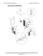
Page 110: ...controls of the Export Administration Regulations EAR This information shall not be provided to non U S persons or transferred by any means to any location outside the United States contrary to the requirements of the EAR Page 110 of 118 9 2 Cooling System Inside Power Supply Flow Diagram ...

Page 111: ...he controls of the Export Administration Regulations EAR This information shall not be provided to non U S persons or transferred by any means to any location outside the United States contrary to the requirements of the EAR Page 111 of 118 9 3 Automatic Gas Console AGC Wiring Diagram ...

Page 112: ...the controls of the Export Administration Regulations EAR This information shall not be provided to non U S persons or transferred by any means to any location outside the United States contrary to the requirements of the EAR Page 112 of 118 9 4 Automatic Gas Console AGC Flow Diagram ...

Page 113: ... the controls of the Export Administration Regulations EAR This information shall not be provided to non U S persons or transferred by any means to any location outside the United States contrary to the requirements of the EAR Page 113 of 118 9 5 Arc Start Console ASC Wiring Diagram ...

Page 114: ...n is subject to the controls of the Export Administration Regulations EAR This information shall not be provided to non U S persons or transferred by any means to any location outside the United States contrary to the requirements of the EAR Page 114 of 118 BLANK PAGE ...

Page 115: ...ily intended for use in an industrial environment There may be potential difficulties in ensuring electromagnetic compatibility in other environments A 2 Installation and Use The user is responsible for installing and using the plasma cutting equipment according to the manufacturer s instructions If electromagnetic disturbances are detected then it shall be the responsibility of the user of the pl...

Page 116: ...ing or other activities are to be carried out The size of the surrounding area to be considered will depend on the structure of the building and other activities that are taking place The surrounding area may extend beyond the boundaries of the premises A 4 Methods of Reducing Emissions A 4 1 Mains Supply Plasma cutting equipment should be connected to the mains supply according to the manufacture...

Page 117: ...e The operator should be insulated from all such bonded metallic components A 4 5 Earthing of the Workpiece Where the workpiece is not bonded to earth for electrical safety nor connected to earth because of its size and position e g ship s hull or building steelwork a connection bonding the workpiece to earth may reduce emissions in some but not all instances Care should be taken to prevent the ea...

Page 118: ...n is subject to the controls of the Export Administration Regulations EAR This information shall not be provided to non U S persons or transferred by any means to any location outside the United States contrary to the requirements of the EAR Page 118 of 118 BLANK PAGE ...

Reviews: