FineLine 300HD Plasma System
BK8053-000107 Rev A.01
This information is subject to the controls of the Export Administration Regulations [EAR]. This information shall not be provided to
non-U.S. persons or transferred by any means to any location outside the United States contrary to the requirements of the EAR.
Page 28 of 118
3.4 Power Supply Input Connections - Primary Power
** Before connecting primary power, check the data plate
on the Power Supply to verify the voltage required **
Refer to chart below for recommended fuse, wire sizes, and type of copper wires. Fuse
the input circuit with the recommended super lag fuses or delay type breakers (also
called “inverse time” or “thermal/magnetic” circuit breakers). Choose input and
grounding wire size according to local or national electric codes. Using input wire sizes,
fuses, or circuit breakers smaller than recommended may result in “nuisance” shut-offs
from high inrush currents, even if the machine is not being used at high currents.
Voltage
Input
Amperes
Fuse
(Super Lag) or
Breaker Size
2
Type 75C Copper Wire in
Conduit AWG (IEC) Sizes
40°C (104°F) Ambient
Type 75C Copper
Ground Wire in Conduit
AWG (IEC) Sizes
380-415V / 3 / 50/60
122
150
1/0 (70)
6 (16)
460V / 3 / 50/60
107
125
1 (50)
6 (16)
575V / 3 / 50/60
93
100
2 (35)
8 (10)
1
Wire and Fuse Sizes based upon the U.S. National Electric Code and maximum output.
2
Also called 'inverse time' or 'thermal/magnetic' circuit breakers; circuit breakers that have a delay in tripping
action that decreases as the magnitude of the current increases.
Connection to the supply circuit can be by means of flexible supply cables or supply
cables through conduit to a permanent installation. The supply cables should have a
600 volt minimum rating and should be sized according to local and national codes.
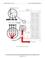
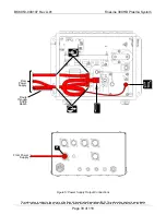
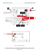
Remove the access panel as shown in Figure 2; replace when installation is complete.
Select Voltage
Set the voltage selection jumper on the Power Supply to match the actual supply
voltage. Refer to Figure 2.
Make Connections
Supply cables are provided by the OEM or end user. Route flexible supply cables
through the strain relief on the back of the Power Supply and connect to the input
terminal block as shown in Figure 2. For supply cables through conduit, install the
conduit in place of the strain relief and connect the associated supply cables to the
input terminal block. Under no circumstances are the supply cables to be routed
through the opening in the Power Supply cabinet without conduit or an appropriate
strain relief as per local and national codes.

