FineLine 300HD Plasma System
BK8053-000107 Rev A.01
This information is subject to the controls of the Export Administration Regulations [EAR]. This information shall not be provided to
non-U.S. persons or transferred by any means to any location outside the United States contrary to the requirements of the EAR.
Page 40 of 118
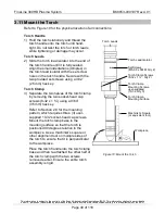
3.11 Mount the Torch
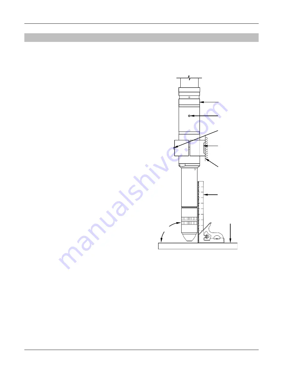
Refer to Figure 10 for the physical location of all connections.
Torch Handle
1) Hold the torch stationary and thread the
torch handle onto the torch until hand-
tight. Do not twist the torch or torch leads
while tightening or damage may occur.
Torch Leads
2) Slide the torch lead isolator into the end of
the torch handle until it is fully seated.
Align the small indentations (dimples) in
the torch lead isolator with the set screw
holes in the torch handle. Secure with the
two provided set screws using a 3/32”
(2.5mm) hex key.
Torch Clamp
3) Separate the two halves of the torch clamp
by removing the two socket-head cap
screws (8-32 x 1 ¾”) using a 9/64”
(3.5mm) hex key.
Refer to Section 2.9 for the mounting
pattern, which requires three (3) user-
supplied 10-32 socket-head cap screws.
Mount the torch clamp base to the
mounting surface so that the torch is
positioned 90 degrees relative to the
workpiece. Use a machinist’s square or
other alignment tool on multiple sides of
the torch to ensure that it is perpendicular
to the workpiece.
Place the torch handle into the torch clamp
base and then re-attached the other half of
the torch clamp with the two screws
removed earlier. Ensure the entire torch
assembly is rigid.
Torch Leads
Set Screws
(M5-0.8 x 5MM, Qty 2)
Torch Clamp
Mounting Screws,
user-supplied
(10-32, Qty 3)
Torch Clamp Screws
(8-32 x 1 ¾”, Qty 2)
Workpiece
Machinist’s Square
(or equivalent tool)
Torch Clamp
Mounting Surface
90°
Torch Lead Isolator
Figure 10: Mount the Torch

