background image

engine adJustment

Adjustments to the engine are to be made only by a Lincoln
Service Center or an authorized Field Service Shop.

battery maintenanCe

To access the battery, remove the battery tray from the front of
the machine with 3/8” nut driver or flat head screw driver. Pull the
tray out of machine far enough to disconnect the negative and
then positive battery cables. The tray can then be tilted and lifted
to remove the entire tray and battery from the machine for easy
service.

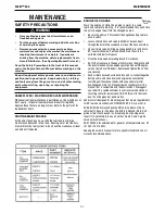
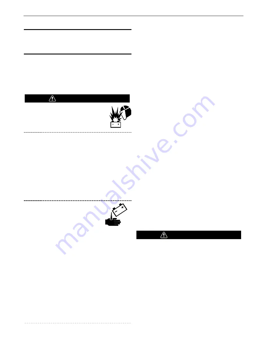
GASES FROM BATTERY can
explode.

Keep sparks, flame and cigarettes away
from battery.

To prevent EXPLOSION when:

INSTALLING A NEW BATTERY — disconnect negative
cable from old battery first and connect to new battery
last.

CONNECTING A BATTERY CHARGER — remove
battery from welder by disconnecting negative cable
first, then positive cable and battery clamp. When
reinstalling, connect negative cable last. Keep well
ventilated.

USING A BOOSTER — connect positive lead to battery
first then connect negative lead to negative battery lead
at engine foot.

BATTERY ACID can burn eyes and
skin.

Wear gloves and eye protection and be
careful when working near battery.

Follow instructions printed on battery.

CLEANING THE BATTERY

Keep the battery clean by wiping it with a damp cloth when dirty.
If the terminals appear corroded, disconnect the battery cables
and wash the terminals with an ammonia solution or a solution of
1/4 pound (0.1113 kg) of baking soda and 1 quart (0.9461L) of
water. Be sure the battery vent plugs (if equipped) are tight so that
none of the solution enters the cells.

After cleaning, flush the outside of the battery, the battery
compartment, and surrounding areas with clear water. Coat the
battery terminals lightly with petroleum jelly or a non-conductive
grease to retard corrosion.

Keep the battery clean and dry. Moisture accumulation on the
battery can lead to more rapid discharge and early battery failure.

CHECKING THE ELECTROLYTE LEVEL

If battery cells are low, fill them to the neck of the filler hole with
distilled water and recharge. If one cell is low, check for leaks.

CHARGING THE BATTERY

When you charge, jump, replace, or otherwise connect battery
cables to the battery, be sure the polarity is correct. Improper
polarity can damage the charging circuit. The Fleet™ 500 positive
(+) battery terminal has a red terminal cover.

If you need to charge the battery with an external charger,
disconnect the negative cable first, then the positive cable before
you attach the charger leads.  After the battery is charged,
reconnect the positive battery cable first and the negative cable
last. Failure to do so can result in damage to the internal charger
components.

Follow the instructions of the battery charger manufacturer for
proper charger settings and charging time.

SERVICING OPTIONAL SPARK ARRESTOR

Clean every 100 hours.

MUFFLER MAY BE HOT

ALLOW ENGINE TO COOL BEFORE INSTALLING THE
SPARK ARRESTER!

DO NOT OPERATE ENGINE WHILE INSTALLING THE
SPARK ARRESTER!

------------------------------------------------------------------------

WARNING

WARNING

D-5

MAINTENANCE

FLEET™ 500

Summary of Contents for Fleet 500

Page 1: ...nes having Code Numbers 12511 Need Help Call 1 888 935 3877 to talk to a Service Representative Hours of Operation 8 00 AM to 6 00 PM ET Mon thru Fri After hours Use Ask the Experts at lincolnelectric...

Page 2: ...A LARGE ROOM OR OUTDOORS natural ventilation may be adequate if you keep your head out of the fumes See below USE NATURAL DRAFTS or fans to keep the fumes away from your face If you develop unusual s...

Page 3: ...rs and devices in position and in good repair Keep hands hair clothing and tools away from V belts gears fans and all other moving parts when starting operating or repairing equipment 1 e In some case...

Page 4: ...to ANSI Z87 I standards 4 b Use suitable clothing made from durable flame resistant material to protect your skin and that of your helpers from the arc rays 4 c Protect other nearby personnel with su...

Page 5: ...nt passing through lifting chains crane cables or other alternate circuits This can create fire hazards or overheat lifting chains or cables until they fail 6 h Also see item 1 c 6 I Read and follow N...

Page 6: ...RIOD B 1 WELDING CONTROLS B 2 ENGINE OPERATION B 3 WELDER OPERATION B 4 AUXILIARY POWER B 5 ACCESSORIES SECTION C MAINTENANCE SECTION D NAMEPLATES WARNING DECALS MAINTENANCE D 1 ROUTINE MAINTENANCE D...

Page 7: ...R Welding Process Welding Output Current Voltage Duty Cycle Output Range Amps Max Weld OCV Voltage 1800RPM DC CONSTANT CURRENT 400A 36V 100 450A 37V 100 500A 33V 100 30A TO 500A 82 VOLTS PEAK TIG 250A...

Page 8: ...nes are designed to run in the level condition which is where the optimum performance is achieved The maximum angle of continuous operation is 20 degrees in all directions 30 degrees Intermittent less...

Page 9: ...ly Fill the fuel tank with clean fresh fuel The capacity of the tank is 25 US gals 94 6 ltrs When the fuel gauge reads empty the tank contains approximately 2 gals 7 6ltrs of reserve fuel Note A fuel...

Page 10: ...be electrically bonded to the metal frame of the vehicle Use a 8 or larger copper wire connected between the machine grounding stud and the frame of the vehicle When this engine driven welder is conn...

Page 11: ...evelop a ground fault If this situation should occur the GFCI will trip removing voltage from the output of the receptacle If a GFCI is tripped see the MAINTENANCE section for detailed information on...

Page 12: ...erfill tank fuel expansion may cause overflow Diesel Fuel Only Low Sulphur Fuel or Ultra Low Sulphur in USA and Canada Remove the fuel tank cap Fill the tank DO NOT FILL THE TANK TO THE POINT OF OVERF...

Page 13: ...ange and in the CC STICK mode This control is not active in the PIPE GOUGE mode when in high range or when in TIG mode CC STICK mode In this mode the ARC FORCE dial sets the short circuit current arc...

Page 14: ...CC STICK PIPE Arc Gouging and TIG modes to be set prior to welding using the OUTPUT control dial During welding the meter display the actual output voltage VOLTS and current AMPS A memory feature hol...

Page 15: ...ctrode sticking Start with the dial set at 0 PIPE GOUGE Mode This slope controlled setting is intended for out of position and down hill pipe welding where the operator would like to control the curre...

Page 16: ...y accepted as a substitute for 2 Thoriated Tungsten in AC and DC applications 3 DCEP is not commonly used in these sizes 4 TIG torch nozzle sizes are in multiples of 1 16ths of an inch 4 1 4 in 6 mm 5...

Page 17: ...can be influenced by many factors including engine maintenance environ mental conditions and fuel quality TABLE B 2 TYPICAL FLEET 500 FUEL CONSUMPTION Test Condition FUEL CONSUMPTION US gal hr litres...

Page 18: ...to the far left click on Equipment click on Engine Driven Welders click on Fleet on next shown scroll down to Fleet 500 Engine Driven Welders 3 Click on VIEW DETAILS 4 The next screen will have an Eq...

Page 19: ...ff Disconnect the negative battery cable to ensure safety Locate oil drain hose and valve in bottom of base and pull through the hole in the case back or side of the base on welder Open oil drain valv...

Page 20: ...f the recommended engine oil Reinstall the oil filler cap and tighten securely Start the engine and check for oil filter leaks Stop the engine and check the oil level If necessary add oil to the upper...

Page 21: ...f and distribute the sealing pressure evenly To complete a tight seal apply pressure by hand at the outer rim of the filter not the flexible center Avoid pushing on the center of the urethane end cap...

Page 22: ...Do not overfill leave room for the fuel to expand Use only fresh No 2D diesel fuel the use of No 1D diesel fuel is recommended in place of No 2D at temperatures below 23 F 5 C Do not use kerosene See...

Page 23: ...pound 0 1113 kg of baking soda and 1 quart 0 9461L of water Be sure the battery vent plugs if equipped are tight so that none of the solution enters the cells After cleaning flush the outside of the b...

Page 24: ...test and reset the GFCI If the GFCI has tripped first carefully remove any load and check it for damage If the equipment has been shut down it must be restarted The equipment needs to be operating at...

Page 25: ...the machine may exhibit Find the listing that best describes the symptom that the machine is exhibiting Step 2 POSSIBLE CAUSE The second column labeled POSSIBLE CAUSE lists the obvious external possib...

Page 26: ...ne will crank but not start 1 Fuel shut off valve on in the OFF position Open valve vertical position of handle 2 Fuel Filters dirty clogged Check and replace main filter element and or Inline Fuel Fi...

Page 27: ...ters as needed 2 Water in fuel If water found in tank Empty fuel tank and refill then purge fuel lines 3 Fuel injector clogged or malfunctioning Battery does not stay charged Engine alternator trouble...

Page 28: ...your local Lincoln Authorized Field Service Facility 2 Air filter clogged clean or replace 3 High idle setting incorrect check and adjust if required 4 Valves out of adjustment 5 Fuel contaminated wit...

Page 29: ...uxiliary power 1 Open circuit breakers Reset breakers If breakers keep tripping reduce power draw 2 GFCI may have tripped Follow GFCI Testing and Resetting Procedure in the MAINTENANCE section of this...

Page 30: ...M9 M4 M3 M2 M1 5 1 5 1 M6 M10 M5 M9 M4 M3 M2 M1 5 1 5 1 M10 M5 M4 M3 M2 M1 1 1 M10 M5 M4 M3 M2 M1 1 1 M10 M5 M4 M3 M2 M1 5 1 5 1 M10 M5 M9 M4 M3 M2 M1 5 1 5 1 M6 M10 M5 M9 M4 M3 M2 M1 5 1 5 1 M4 M5 M...

Page 31: ...TER OF GRAVITY WITH OIL IN ENGINE AND EMPTY FUEL TANK 36 91 937 6 39 91 1013 7 1 34 34 2 22 50 571 5 45 96 1167 4 65 00 1651 30 00 762 1 59 50 1511 3 28 82 732 1 27 00 685 8 N A 33 50 850 9 33 75 857...

Page 32: ...NECT THE NEGATIVE BATTERY CABLE 2 REMOVE THE SCREWS THAT SECURE THE UPPER CONTROL PANEL AND OPEN THE PANEL 3 WHILE HOLDING THE RCD MOUNTING BRACKET REMOVE THE TWO SCREWS SECURING THE COVER PLATE AND R...

Page 33: ...RAL STUD TO RCD N BOTTOM 9 COAT AREA WHERE LEADS CONNECT TO RCD WITH A SILICONE RUBBER RTV SEALANT 10 MOUNT RCD PROTECTIVE BOOT TO PANEL USING MOUNTING BRACKET SCREWS SET ASIDE IN STEP 3 11 CHECK WIRI...

Page 34: ...RECEPTACLE PANEL GND G GND G GND E GND E LINE 6K LOAD HOT WHITE GFCI 6G 6F 5C 5B 5B 6G 5W 6L 5W 5 STATOR AUXILIARY WINDINGS 5A RCD N 1 N 2 5D 5D 5E 5E TWIST LEADS 5D 5E BEFORE INSERT INTO RCD N POSIT...

Page 35: ...parts or electrode with skin or wet clothing l Insulate yourself from work and ground l No toque las partes o los electrodos bajo carga con la piel o ropa moja da l Aislese del trabajo y de la tierra...

Page 36: ...d Entl ftung des Arbeitsplatzes l Mantenha seu rosto da fuma a l Use ventila o e exhaust o para remover fumo da zona respirat ria l Turn power off before servicing l Desconectar el cable de ali mentac...

Page 37: ...ch information or advice As a matter of practical consideration we also cannot assume any respon sibility for updating or correcting any such information or advice once it has been given nor does the...

Reviews: