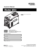
background image

Operator’s Manual

Flextec

®

650x

Register your machine:  

www.lincolnelectric.com/register

Authorized Service and Distributor Locator:  

www.lincolnelectric.com/locator

IM10373

|   Issue D ate Jun-18

© Lincoln Global, Inc.  All Rights Reserved.

For use with machines having Code Numbers:

12596

Save for future reference  

Date Purchased

Code: (ex: 10859)

Serial: (ex: U1060512345)

Summary of Contents for Flextec 650x

Page 1: ...m register Authorized Service and Distributor Locator www lincolnelectric com locator IM10373 Issue Date Jun 18 Lincoln Global Inc All Rights Reserved For use with machines having Code Numbers 12596 S...

Page 2: ...A LARGE ROOM OR OUTDOORS natural ventilation may be adequate if you keep your head out of the fumes See below USE NATURAL DRAFTS or fans to keep the fumes away from your face If you develop unusual s...

Page 3: ...hot engine parts and igniting Do not spill fuel when filling tank If fuel is spilled wipe it up and do not start engine until fumes have been eliminated 1 d Keep all equipment safety guards covers and...

Page 4: ...m to ANSI Z87 I standards 4 b Use suitable clothing made from durable flame resistant material to protect your skin and that of your helpers from the arc rays 4 c Protect other nearby personnel with s...

Page 5: ...nt passing through lifting chains crane cables or other alternate circuits This can create fire hazards or overheat lifting chains or cables until they fail 6 h Also see item 1 c 6 I Read and follow N...

Page 6: ...duct Description B 2 Duty Cycle B 2 Design Features B 2 Recommended Processes and Equipment B 3 Case Front Controls B 4 Case Back Controls B 5 Internal Controls B 6 Power Up Sequence B 7 Common Weldin...

Page 7: ...the U S National Electric Code and maximum output for 40 C 104 ambient 2 Also called inverse time or thermal magnetic circuit breakers circuit breakers that have a delay in tripping action that decrea...

Page 8: ...V OUTPUT RANGE AMPERES 40 815 10 815 15 815 40 815 40 815 40 815 OCV Uo 60 24 60 60 60 60 OCV Ur 15 15 WELDING PROCESS IP23 180 H Insulation Class Weight does not include input cord Power Source is de...

Page 9: ...hese precautions can result in excessive operating temperatures and nuisance shutdowns LIFTING The FLEXTEC 650x has 2 lifting eyelets and 2 handles that can be used to lift the machine Both handles or...

Page 10: ...ELECTION Welders are shipped connected for 460 Volt input voltage To accomodate different input voltages move the reconnect lead to the corresponding voltage see Figure A 1 Refer to Auxiliary Reconnec...

Page 11: ...D 40Vdc E 40Vdc Common 12 PIN ACCESSORY CONNECTIVITY Function Pin Wiring 12 pin remote control connector for remote or hand foot amptrol and digital accessories A ArcLink CAN B ArcLink CAN C Remote po...

Page 12: ...onnections Route all cables directly to the work and wire feeder avoid excessive lengths and do not coil excess cable Route the electrode and work cables in close proximity to one another to minimize...

Page 13: ...leled for increased output requirements No kit is required for paralleling of FLEXTEC 650x power sources The FLEXTEC 650X can only be paralleled for constant current processes mode switch must be in t...

Page 14: ...F 74 TO THE FLEXTEC 650x CONTROL SETTING 14 PIN CONTROL CABLE K1797 XX WIRE FEEDER ELECTRODE WORK LF 72 LF 74 Flextec 650x WELD MODE WELD TERMINALS REMOTE LOCAL VOLTMETER POLARITY CV CV INNERSHIELD OF...

Page 15: ...3 Locate the two 8 pole DIP switches near the top left corner of the LN 10 DH 10 Control P C board labeled S1 and S2 4 Switch settings are only programmed during input power up restoration Setting th...

Page 16: ...97 XX Flextec 650x Flextec 650x CONTROL SETTING WELD MODE WELD TERMINALS REMOTE LOCAL VOLTMETER POLARITY CV CV INNERSHIELD ON LOCAL PROCESS DEPENDENT CONTROL SETTING WELD MODE WELD TERMINALS REMOTE LO...

Page 17: ...820 XX ELECTRODE WIRE FEEDER LN 8 LN 9 WORK Flextec 650x Flextec 650x CONTROL SETTING WELD MODE WELD TERMINALS REMOTE LOCAL VOLTMETER POLARITY CV CV INNERSHIELD OFF LOCAL PROCESS DEPENDENT CONTROL SET...

Page 18: ...N FOR NA 5 WIRE FEEDER ONLY MOVE BLUE JUMPER LEAD ON VOLTAGE BOARD TO AUTO TERMINAL Flextec 650x 14 PIN CONTROL CABLE K1822 XX ELECTRODE TRACTOR LT 7 WORK Flextec 650x CONTROL SETTING WELD MODE WELD T...

Page 19: ...g ceases Do not touch electrically live parts or electrodes with your skin or wet clothing Insulate yourself from the work and ground Always wear dry insulating gloves FUMES AND GASES can be danger ou...

Page 20: ...REAKER WIRE FEEDER POSITIVE OUTPUT NEGATIVE OUTPUT 3 PHASE INVERTER INPUT POWER THREE PHASE DIRECT CURRENT OPEN CIRCUIT VOLTAGE REDUCED OPEN CIRCUIT VOLTAGE INPUT VOLTAGE OUTPUT VOLTAGE INPUT CURRENT...

Page 21: ...perator in mind Getting setup for the weld is several clicks away and even the most novice welder can be confident he is setup properly F A N fan as needed Cooling fan runs when the output is energize...

Page 22: ...he selected weld process 8 Arc Force Control Dial 9 Positive and Negative output studs 10 Wire Feeder Voltmeter polarity selection switch 11 115V or 42V wire feeder selector switch 12 14 pin wire feed...

Page 23: ...g the machine 3 Input Power Reconnect Configures the machine for the input supply voltage 4 OPTION GFCI protection for the 115V auxiliary output not shown 5 115 volt 15 amp auxiliary output duplex wit...

Page 24: ...on See Figure B 5 2 Enable Multi Weld Mode Turn switch 3 to the ON Position See Figure B 6 3 Current Voltage Calibration Setting Turn switch 1 to the ON Position See Figure B 7 Factory Default Setting...

Page 25: ...Switch 6 Position switch used to select the welding process Hot Start Control Dial The Hot Start control regulates the starting current at arc initiation Hot Start can be set to 0 and no additional c...

Page 26: ...15 amps It is intended for the SMAW stick welding processes and arc gouging Output Control Local Remote When the control is set to local no remote potentiometer control plugged into the 12 pin or 14 p...

Page 27: ...welding amperage The remote potentiometer controls the amperage from minimum to this pre set maximum CV Gas This weld mode is a constant voltage CV mode featuring continuous control from 10 to 45 vol...

Page 28: ...s switch to Remote when an external potentiometer control is connected Output Control Dial When the Local Remote is set to local this dial sets the welding voltage When the Local Remote is set to Remo...

Page 29: ...emote Not used for this welding process Output Control Dial Not used for this welding process CrossLinc CrossLinc is a new welding system communication technology When using a CrossLinc enabled power...

Page 30: ...utput Order K857 2 for 25 ft 7 6 m Order K857 1 for 100 ft 30 m Requires K2909 1 12 pin to 6 pin Adapter TIG Options Pro Torch TIG Torches PTA 9 PTA 17 PTA 26 2 piece power cord Foot Amptrol Provides...

Page 31: ...the duty cycle and output rating If excessive operating temperature should occur the thermostat will prevent output voltage or current The meter will remain energized during this time Thermostats are...

Page 32: ...eing calibrated remove the right case side to provide access to the User Interface Set position 1 on the dip switch back to OFF VOLTAGE CALIBRATION COMPLETE TO RESTORE FACTORY CURRENT CALIbRATION 1 Co...

Page 33: ...olumn describes possible symptoms that the machine may exhibit Find the listing that best describes the symptom that the machine is exhibiting Step 2 POSSIBLE CAUSE The second column labeled POSSIBLE...

Page 34: ...Err see the fault section for corrective action 2 If the thermal LED is lit refer to the thermal section 3 If the output terminals are in remote control switch to ON and check for output voltage If o...

Page 35: ...to reset 36 Thermal Fault Machine shut off output due to elevated internal temperatures 1 Check for material blocking intake or exhaust louvers Blow air in the rear louvers to clear dirt from the fan...

Page 36: ...575V F1 WIRE FEEDER SELECT S8 CB2 15A CIRCUIT BREAKER 115V RECEPTACLE J50 TO A SYSTEM GROUND PER NATIONAL ELECTRICAL CODE G 31F 31B 32A 3 5A CB3 317 316 280A 280A N C THERMOSTAT 3 TURNS FAN ON BUT DOE...

Page 37: ...F 2 DIAGRAMS FLEXTEC 650x L16096 2 A 01 15 97 15 09 26 85 29 31 21 16 21 83 23 66...

Page 38: ...Flextec 650x 12596...

Page 39: ...AR 1 P 1101 C CASE FRONT ASSEMBLY AR 2 P 1101 D DIVIDER PANEL ASSEMBLY AR 3 P 1101 E BASE ASSEMBLY AR 4 P 1101 F CASE BACK ASSEMBLY AR 5 P 1101 G COVERS ASSEMBLY AR Index of Sub Assemblies 12596 Flext...

Page 40: ...P 1101 A jpg Index of Sub Assemblies 12596 2 Flextec 650x 12596 Printed 01 03 2017 at 13 39 33 Produced by Enigma...

Page 41: ...SS23093 1 LED LENS CLEAR 1 9SS23094 1 RETAINING O RING 1 9SG8738 MAIN CONTROL HARNESS 1 11A 9SS12021 70 BOX RECEPTACLE SOLID SHELL 1 11B 9SS12021 73 BOX RECEPTACLE SOLID SHELL 1 11C 9SS12021 78 CABLE...

Page 42: ...SSEMBLY 1 21A 9SS20030 1 LINE SWITCH 1 21B 9SS25384 1 SWITCH COVER WEATHER RESISTANT 1 9SCF000373 10 32X 50PRHS FULL GR2 4265 2 9ST9695 1 LOCKWASHER 2 22A 9SS28393 5 NOISE SUPPRESSOR 1 9SS9262 1 PLAIN...

Page 43: ...P 1101 C jpg Case Front Assembly Flextec 650x 12596 5 Printed 01 03 2017 at 13 39 33 Produced by Enigma...

Page 44: ...RACKET 1 9SS9225 68 THREAD FORMING SCREW CUTTING 4 6 9ST12380 4 BUSHING 3 7A 9SM19656 RECONNECT PANEL 1 7B 9ST14530 1 RECEPTACLE 3 7C 9SS28845 RECONNECT NAMEPLATE 1 7D 9ST9187 13 10 24HLN 1817 1 NYLON...

Page 45: ...ACITOR INSULATION 1 9SE106A 2 LOCKWASHER 2 9SCF000017 1 4 20HN 2 19A 9SS18504 6 CURRENT TRANSDUCER 1 9SS28515 TRANSDUCER SPACER 2 9SS9225 36 THREAD FORMING SCREW CUTTING 2 20A 9ST14605 INSULATOR 2 20B...

Page 46: ...P 1101 D jpg Divider Panel Assembly 8 Flextec 650x 12596 Printed 01 03 2017 at 13 39 33 Produced by Enigma...

Page 47: ...MING SCREW 4 9SS9262 98 PLAIN WASHER 4 9SS9262 1 PLAIN WASHER 1 9SE106A 15 LOCKWASHER 1 9SCF000344 HEX HD SCREW 1 6A 9SG6954 2 TRANSFORMER ASSEMBLY 1 9SS9225 66 SELF TAPPING SCREW 3 9SL16016 OUTPUT RE...

Page 48: ...SCREW 2 8A 9SG8746 SWITCH BOARD ASSEMBLY 1 8B 9SS9225 66 SELF TAPPING SCREW 2 9A 9SS23224 BUS BAR 1 9B 9SCF000028 5 16 18X1 25HHCS 2 9C 9SS9262 30 PLAIN WASHER 4 9D 9SE106A 3 LOCKWASHER 2 9E 9SCF0000...

Page 49: ...P 1101 E jpg Base Assembly Flextec 650x 12596 11 Printed 01 03 2017 at 13 39 33 Produced by Enigma...

Page 50: ...9SS19999 3 CORD GRIP CONNECTOR 1 6B 9ST14370 6 CONDUIT LOCKNUT 1 7A 9ST12287 22 CIRCUIT BREAKER 15A 1 7B 9SS22061 1 CIRCUIT BREAKER BOOT 1 8A 9SM22692 HANDLE SUPPORT BRACKET 1 8B 9SG6525 3 HANDLE 1 8C...

Page 51: ...P 1101 F jpg Case Back Assembly Flextec 650x 12596 13 Printed 01 03 2017 at 13 39 33 Produced by Enigma...

Page 52: ...CASE SIDE 1 2A 9SG7030 CASE TOP WRAPAROUND 1 9SS9225 66 SELF TAPPING SCREW 6 9SG8737 WIRING DIAGRAM 1 6 9SL8064 1 WARNING DECAL INTERNATIONAL 1 7 9SS30277 2 WARRANTY DECAL 1 8 9SM22461 FAMILY NAME DE...

Page 53: ...P 1101 G jpg Covers Assembly Flextec 650x 12596 15 Printed 01 03 2017 at 13 39 33 Produced by Enigma...

Page 54: ...parts or electrode with skin or wet clothing l Insulate yourself from work and ground l No toque las partes o los electrodos bajo carga con la piel o ropa moja da l Aislese del trabajo y de la tierra...

Page 55: ...d Entl ftung des Arbeitsplatzes l Mantenha seu rosto da fuma a l Use ventila o e exhaust o para remover fumo da zona respirat ria l Turn power off before servicing l Desconectar el cable de ali mentac...

Page 56: ...to such information or advice As a matter of practical consideration we also cannot assume any respon sibility for updating or correcting any such information or advice once it has been given nor doe...

Reviews: