background image

English  

English 

2


SAFETY MARK:  This equipment is suitable for supplying power for welding operations carried out in 
an environment with increased hazard of electric shock. 


EQUIPMENT WEIGHT OVER 30kg:  Move this equipment with care and with the help of another 
person.  Lifting may be dangerous for your physical health. 


CYLINDER MAY EXPLODE IF DAMAGED:  Use only compressed gas cylinders containing the 
correct shielding gas for the process used and properly operating regulators designed for the gas and 
pressure used.  Always keep cylinders in an upright position securely chained to a fixed support.  Do 
not move or transport gas cylinders with the protection cap removed.  Do not allow the electrode, 
electrode holder, work clamp or any other electrically live part to touch a gas cylinder.  Gas cylinders 
must be located away from areas where they may be subjected to physical damage or the welding 
process including sparks and heat sources. 

HF 

CAUTION:  The high frequency used for contact-free ignition with TIG (GTAW) welding, can interfere 
with the operation of insufficiently shielded computer equipment, EDP centers and industrial robots, 
even causing complete system breakdown.  TIG (GTAW) welding may interfere with electronic 
telephone networks and with radio and TV reception. 


Installation and Operator Instructions 

 
Read this entire section before installation or operation 
of the machine. 
 

Location and Environment 

This machine will operate in harsh environments.  
However, it is important that simple preventative 
measures are followed to assure long life and reliable 
operation. 


Do not place or operate this machine on a surface 
with an incline greater than 15° from horizontal. 


Do not use this machine for pipe thawing. 


This machine must be located where there is free 
circulation of clean air without restrictions for air 
movement to and from the air vents.  Do not cover 
the machine with paper, cloth or rags when 
switched on. 


Dirt and dust that can be drawn into the machine 
should be kept to a minimum. 


This machine has a protection rating of IP23.  Keep 
it dry when possible and do not place it on wet 
ground or in puddles. 


Locate the machine away from radio controlled 
machinery.  Normal operation may adversely affect 
the operation of nearby radio controlled machinery, 
which may result in injury or equipment damage.  
Read the section on electromagnetic compatibility in 
this manual. 


Do not operate in areas with an ambient 
temperature greater than 40°C. 


Input Supply Connection 

Check the input voltage, phase, and frequency supplied 
to this machine before turning it on.  The allowable input 
voltage is indicated in the technical specification section 
of this manual and on the rating plate of the machine.  
Be sure that the machine is grounded. 

 
Make sure the amount of power available from the input 
connection is adequate for normal operation of the 
machine.  The fuse rating and cable sizes are both 
indicated in the "Technical Specification" section of this 
manual. 
 
The machines are designed to operate on engine driven 
generators as long as the auxiliary can supply adequate 
voltage, frequency and power as indicated in the 
"Technical Specification" section of this manual.  The 
auxiliary supply of the generator must also meet the 
following conditions: 


Vac peak voltage:  below 670V 


Vac frequency:  in the range of 50 and 60Hz 


RMS voltage of the AC waveform:  400Vac ± 15% 

 
It is important to check these conditions because many 
engine driven generators produce high voltage spikes.  
Operation of this machine on engine driven generators 
not conforming to these conditions is not recommended 
and may damage the machine. 
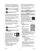
 

Output Connections 

A quick disconnect system using Twist-Mate

 cable 

plugs is used for the welding cable connections.  Refer 
to the following sections for more information on 
connecting the machine for operation of stick welding 
(MMA) or TIG welding (GTAW).  


(+) Positive Quick Disconnect:  Positive output 
connector for the welding circuit. 


(-) Negative Quick Disconnect:  Negative output 
connector for the welding circuit. 


Stick Welding (MMA) 

This machine does not include a MMA welding kit 
cables, but may be purchased separately.  Refer to the 
accessories section for more information. 

Summary of Contents for INVERTEC 300TPX

Page 1: ...IM2041 03 2014 REV02 INVERTEC 300TPX 400TPX OPERATOR S MANUAL ENGLISH Lincoln Electric Bester Sp z o o ul Jana III Sobieskiego 19A 58 263 Bielawa Poland www lincolnelectric eu ...

Page 2: ...hine INVERTEC 300TPX conforms to the following directives 2006 95 CEE 2004 108 CEE and has been designed in compliance with the following standards EN 60974 1 EN 60974 10 2007 15 02 2013 Paweł Lipiński Operations Director Lincoln Electric Bester Sp z o o ul Jana III Sobieskiego 19A 58 263 Bielawa Poland 07 11 ...

Page 3: ...chine INVERTEC 400TPX conforms to the following directives 2006 95 CEE 2004 108 CEE and has been designed in compliance with the following standards EN 60974 1 EN 60974 10 2007 15 02 2013 Paweł Lipiński Operations Director Lincoln Electric Bester Sp z o o ul Jana III Sobieskiego 19A 58 263 Bielawa Poland 07 11 ...

Page 4: ...e dealer For future reference record in the table below your equipment identification information Model Name Code Serial Number can be found on the machine rating plate Model Name Code Serial number Date Where Purchased ENGLISH INDEX Safety 1 Installation and Operator Instructions 2 Electromagnetic Compatibility EMC 14 Technical Specifications 15 WEEE 15 Spare Parts 15 Electrical Schematic 16 Sugg...

Page 5: ...MAGNETIC FIELDS MAY BE DANGEROUS Electric current flowing through any conductor creates electric and magnetic fields EMF EMF fields may interfere with some pacemakers and welders having a pacemaker shall consult their physician before operating this equipment CE COMPLIANCE This equipment complies with the European Community Directives ARTIFICIAL OPTICAL RADIATION According with the requirements in...

Page 6: ...ept to a minimum This machine has a protection rating of IP23 Keep it dry when possible and do not place it on wet ground or in puddles Locate the machine away from radio controlled machinery Normal operation may adversely affect the operation of nearby radio controlled machinery which may result in injury or equipment damage Read the section on electromagnetic compatibility in this manual Do not ...

Page 7: ...tomatically turned ON and OFF in order to ensure the torch cooling When Stick welding mode is used the cooler will be OFF This machine does not include a cooled TIG torch but one may be purchased separately Refer to the accessories section for more information WARNING The Machine is provided with an electrical connection for the Coolarc unit on its rear side This socket is ONLY for the connection ...

Page 8: ...rates in two different modes STICK and TIG STICK mode with a Remote command connected the output of the machine is ON A Remote Amptrol or Pedal are allowed trigger is ignored Connecting the Remote command excludes the Output Current Knob of the Machine s user interface Through the Remote command is available the full Output Current Range TIG mode in Local and remote mode the output of the machine ...

Page 9: ...rrent knob sets the output current Memory Pushbuttons These pusbuttons allows to store M or recall M TIG welding programs 10 memory records P01 to P10 are available for the user To store or recall a record Store M Recall M 01 10 Store M Recall M Keep pushed for 4s The Memory pushbuttons are disabled during welding See List of parameters and Factory stored programs section below for a complete list...

Page 10: ...rode holder Auto Adaptive Arc Force this function increases temporary the output current used to clear intermittent connections between the electrode and the weld puddle that occur during stick welding This is an active control feature that guarantees the best arrangement between the arc stability and spatter presence The feature Auto Adaptive Arc Force has instead of a fixed or manual regulation ...

Page 11: ... the TIG arc will remain on for 3 seconds if the arc is not started in this time limit the trigger sequence must be restarted The HF arc start strength can be adjusted in the setup menu by changing the value of option 40 Six arc start strengths are available ranging from 1 smooth suitable for thin electrodes to 6 strong suitable for thick electrodes The default value for this option is 3 Spot TIG ...

Page 12: ...rrent value after the Downslope For an explanation of the Crater operation refer to the trigger sequences explained below 7 POSTFLOW In the TIG welding modes this function controls the shielding gas Postflow time In Stick welding mode this is not used During welding the Sel pushbutton is enabled for the following functions Output current Only if Pulse Function is active is possible operates on the...

Page 13: ...lding mode selected the following welding sequence will occur 1 Press and hold the TIG torch trigger to start the sequence The machine will open the gas valve to start the flow of the shielding gas After the preflow time to purge air from the torch hose the output of the machine is turned ON At this time the arc is started according to the selected welding mode After the arc is started the output ...

Page 14: ... hold the TIG torch trigger another time to end the downslope time and maintain the output current at the Crater current When the TIG torch trigger is released the output will again increase to the Welding current like in step 4 to continue welding When the main part of the weld is complete go to step 3 As shown here again after the TIG torch trigger is quickly pressed and released from step 3A it...

Page 15: ...machine wait for a few seconds then turn ON again If the error remains a maintenance is required Please contact the nearest technical service center or Lincoln Electric and report the error code displayed on the meter of the Front Panel Error code table 01 Input out of range LED is blinking Indicates that an Input Voltage Overrange protection is active the Machine restarts automatically when the I...

Page 16: ...ance operations may vary in accordance with the working environment Any noticeable damage should be reported immediately Check cables and connections integrity Replace if necessary Keep clean the machine Use a soft dry cloth to clean the external case especially the airflow inlet outlet louvers WARNING Do not open this machine and do not introduce anything into its openings Power supply must be di...

Page 17: ...round 30 10 90 step 1 Current selected value Downslope 0s 0 20s step 0 1s Current selected value s Crater 30 5 100 Current selected value A Postflow 10s 0 30s step 1s Current selected value s Stick Welding SOFT and CRISP programs Parameter Features Selectable Value Range Displayed parameter name Displayed value Soft Stick Hot start Anti Sticking and Arc Force are automatically adjusted by the mach...

Page 18: ...uipment to ensure by consultation with the distribution network operator if necessary that the equipment may be connected Before installing the machine the operator must check the work area for any devices that may malfunction because of electromagnetic disturbances Consider the following Input and output cables control cables and telephone cables that are in or adjacent to the work area and the m...

Page 19: ...0 C Storage Temperature 25 C to 55 C WEEE 07 06 English Do not dispose of electrical equipment together with normal waste In observance of European Directive 2002 96 EC on Waste Electrical and Electronic Equipment WEEE and its implementation in accordance with national law electrical equipment that has reached the end of its life must be collected separately and returned to an environmentally comp...

Page 20: ...und cable 300A 50mm 2 10m GRD 400A 70 5M 400TPX Ground cable 400A 70mm 2 5m GRD 400A 70 10M 400TPX Ground cable 400A 70mm 2 10m GRD 400A 70 15M 400TPX Ground cable 400A 70mm 2 15m K10513 26 4 300TPX 400TPX Air cooled TIG torch LT 26 G 180A 4m K10513 26 8 300TPX 400TPX Air cooled TIG torch LT 26 G 180A 8m K10513 18 4 300TPX 400TPX Water cooled TIG torch LT 18 W 320A 4m K10513 18 8 300TPX 400TPX Wat...

Reviews: