A-4
INSTALLATION
V155-S
A-4
TIG WELDING
This machine does not have a built in Gas Solenoid
so a one piece gas valve TIG Torch is required. A
K960-2 Twist-mate TIG Torch adapter is also required.
Refer to the accessories section for more information
about TIG Torches and required Twist-mate adapter.
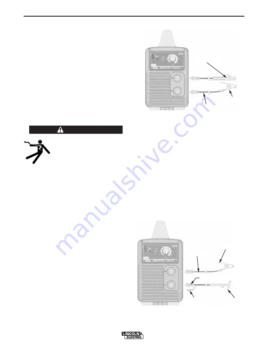
Most TIG welding is done with DC(-) polarity shown
here. If DC(+) polarity is necessary switch the cable
connections at the machine. (See Figure A.2)
Connect the torch cable to the (-) terminal of the
machine and the work clamp to the (+) terminal.
Insert the connector with the key lining up with the
keyway and rotate approximately 1/4 turn clockwise.
Do not over tighten. Finally, connect the Twist-mate
adapter gas hose to the gas regulator on the cylinder
of gas to be used.
FIGURE A.2
Work Clamp
Twist-mate Adapter K-960-2
Work Cable
Gas Valve
TIG Torch
Gas Hose
To Bottle
ARFU (Auto-Restore Fuse)
The dual input voltage machine is provided with the
ARFU device. It operates only when the input is con-
nected to the 120Vac mains and protects from input
overcurrent. When active, the "Thermal LED" lights
(see "Controls and Operational Features" in the
Operation Section).
Note: The ARFU device operates independently from
the machine's duty-cycle.
OUTPUT CONNECTIONS
A quick disconnect system using Twist-Mate™ cable
plugs is used for the welding cable connections.
Refer to the following sections for more information on
connecting the machine for operation of stick welding
(MMA) or TIG welding.
ELECTRIC SHOCK can kill.
• Keep the electrode holder and
cable insulation in good condition.
• Do not touch electrically live parts
or electrode with skin or wet cloth-
ing.
• Insulate yourself from work and ground.
• Turn the input line Switch on the Invertec V155-
S “off” before connecting or disconnecting out-
put cables or other equipment.
-----------------------------------------------------------
STICK WELDING (MMA)
First determine the proper electrode polarity for the elec-
trode to be used. Consult the electrode data for this
information. Then connect the output cables to the out-
put terminals of the machine for the selected polarity.
Shown here is the connection method for DC(+) welding.
(See Figure A.1)
Connect the electrode cable to the (+) terminal and the
work clamp to the (-) terminal. Insert the connector with
the key lining up with the keyway and rotate approxi-
mately 1/4 turn clockwise. Do not over tighten.
For DC(-) welding, switch the cable connections at the
machine so that the electrode cable is connected to (-)
and the work clamp is connected to (+).
Work Clamp
Work Cable
Electrode
Holder
FIGURE A.1
WARNING
Summary of Contents for INVERTEC V155-S 11326
Page 6: ...v SAFETY v EN 60974 10...
Page 7: ...vi SAFETY vi EN 60974 10...


