background image

A-9

INSTALLATION

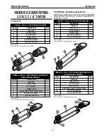
FUME EXTRACTION ARMS

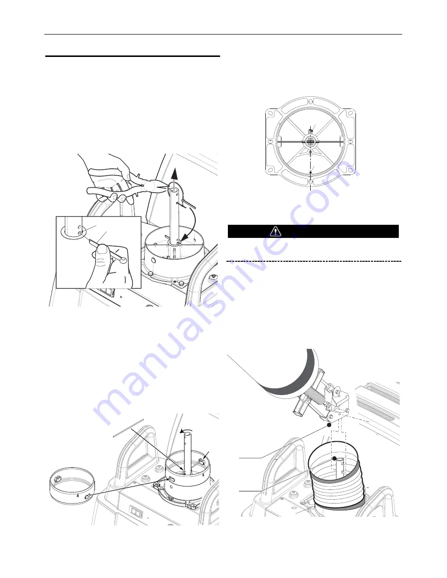
MoUntinG tHe lfa 3.1 or 4.1 arM 

to tHe MobifleX

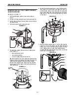
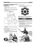
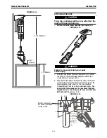
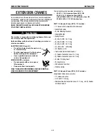
See Figure A.7 for steps 1-4

1.  Cut through the upper cable tie to release the cotter pin 

(Item A).

2.  Lift the post of the base swivel mount by the lower cable tie.  

3.  Put the cotter pin through the lowest hole in the post (Item B)

and bend it around. 

4.  Cut the lower cable tie and let down the post.  

FIGURE A.7

5.  Remove clamping pin from under arm seal band of the base

swivel mount.

6.  Fold down the arm seal band and take off the red plastic ring.

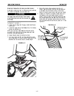
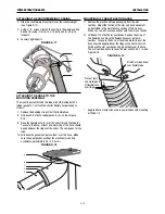
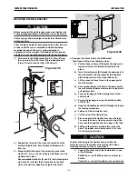
See Figure A.8 for steps 7-8

7.  Insert the clamping pin (Item A) through the hole in the post

located above the split pin.

8.  Position the red plastic ring (Item B) and place the clamping

pin into the ridges (Item C).  Rotating the red plastic ring may
be necessary.

FIGURE A.8

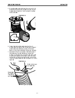
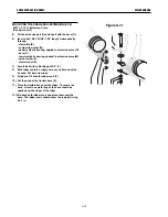
See Figure A.9 for steps 9-12

9.  Turn the base swivel mount so, that the stop pin (A) is in line

with the cable lead-through hole (B).

FIGURE A.9

Note: 

The supply cable inside the base swivel mount of the

Mobiflex 200 OR 200 HE Base Unit is not used when mounting a
K2633-5 or K2633-7 LFA 3.1/4.1 Mobile Manual arm.

Do not remove the yellow tape attaching both arm sections.

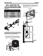
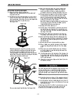
See Figure A.10 for steps 1-3

1.  Mount the extraction arm LFA 3.1/4.1 Mobile Manual (A) on

the post (B) using the two 5/16-18 bolts and two self-locking
5/16-18 nuts with washers.

2. Remove the yellow tape from both arm sections.

3.   Proceed to Balance Check and adjust the friction of the arm

and hood movement as described in the maintenance section
of this manual.

FIGURE A.10

A

B

A

B

C

A

B

WARNING

B

A

Summary of Contents for K1655-10-LTA 2.0

Page 1: ...A 3 1 10FT with Flange K1655 9 LFA 4 1 13FT with Flange K1655 10 LTA 2 0 6 5FT Telescopic K1655 14 LTA 2 0 CW 6 5FT Telescopic K1655 12 LFA 2 0 6 5FT with Flange K1655 13 LFA 4 1 LC 13FT with Flange F...

Page 2: ...A LARGE ROOM OR OUTDOORS natural ventilation may be adequate if you keep your head out of the fumes See below USE NATURAL DRAFTS or fans to keep the fumes away from your face If you develop unusual s...

Page 3: ...hot engine parts and igniting Do not spill fuel when filling tank If fuel is spilled wipe it up and do not start engine until fumes have been eliminated 1 d Keep all equipment safety guards covers and...

Page 4: ...m to ANSI Z87 I standards 4 b Use suitable clothing made from durable flame resistant material to protect your skin and that of your helpers from the arc rays 4 c Protect other nearby personnel with s...

Page 5: ...nt passing through lifting chains crane cables or other alternate circuits This can create fire hazards or overheat lifting chains or cables until they fail 6 h Also see item 1 c 6 I Read and follow N...

Page 6: ...used to capture welding fume at or near the arc and filter contaminants out of the air The ventilation or exhaust needed for your application depends upon many factors such as Workspace volume Worksp...

Page 7: ...http www aws org Supplemental Information Not listed Nuisance value maximum is 10 milligrams per cubic meter PEL value for iron oxide is 10 milligrams per cubic meter TLV value for iron oxide is 5 mil...

Page 8: ...A 2 0 A 16 WALL MOUNTING LFA 4 1 LC A 18 EXTENSION CRAMNES A 20 OPERATION B 1 GRAPHIC SYMBOLS THAT APPEAR ON THIS MACHINE OR IN THIS MANUAL B 1 GENERAL DESCRIPTION B 1 MANUAL OPERATION B 1 USERS B 1 I...

Page 9: ...mounted Fan Extracted air can be vented outside through the Air Exhaust Silencer or filtered through a Statiflex 200 M or 400 MS Wall Mounted Filter Unit The Starter Overload Switch for the SF2400 Ext...

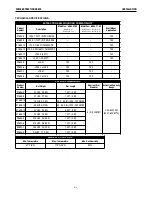
Page 10: ...YES K2633 6 LFA 3 1 w LAS YES YES K2633 7 LFA 4 1 YES YES K2633 8 LFA 4 1 w LAS YES YES PHYSICAL DIMENSIONS Product Number Net Weight Arm Length Nominal Arm Diameter Extraction Capacity Range K1655 8...

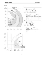
Page 11: ...8 ft 2 4 m 4 ft 1 2 m 0 ft 0 m 79 2000 mm 8 200 mm 79 2000 mm 79 2000 mm LFA 3 1 130 in LFA 4 1 170 in With LFA 3 1 287 in 7300 mm With LFA 4 1 327 in 8300 mm 7 9 2 0 0 0 m m 79 2000 mm 8 200 mm 79 2...

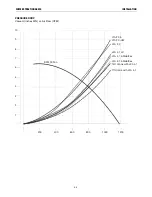
Page 12: ...RACTION ARMS Vacuum inches WG vs Air Flow CFM 200 1 2 3 4 5 6 7 8 9 10 400 600 SF2400 Fan LTA 2 0 LTA 2 0 CW LFA 4 1 Mobiflex LFA 4 1 LC LFA 3 1 Mobiflex 14ft Crane with LFA 4 1 7ft Crane with LFA 4 1...

Page 13: ...ng environment Protect the product against water and humidity Make sure the room is always sufficiently ventilated this applies especially to confined spaces The installer is responsible for following...

Page 14: ...for Operator Manual IM10320 SF2400 Stationary Fan NOT SHOWN See Parts Page for Hardware Bag Contents K1655 8 LFA 3 1 10FT EXTRACTION ARM ITEM DESCRIPTION QTY 1 ARM BODY 1 2 HOSE SUPPORT 1 3 HOOD ASSE...

Page 15: ...g rod and snapping it into place on the U shaped indents on the red plastic ring The lip of the ring should fit securely against the top edge of the mounting assembly yet rotate with the rod FIGURE A...

Page 16: ...set seal all hose connections with the arm seal bands 7 Fold back 2 3 of both arm seal bands Remove the wrap of the flexible hose Place the flexible hose over both arm sections To secure the hose at...

Page 17: ...HOSE SUPPORT 1 3 HOOD ASSEMBLY 1 4 FLEXIBLE HOSES 2 5 INSTRUCTION MANUAL 1 6 LOOSE HARDWARE BAG 1 K2633 6 LFA 3 1 10FT EXTRACTION ARM WITH LAMP AND ARC SENSOR ITEM DESCRIPTION QTY 1 ARM BODY 1 2 HOSE...

Page 18: ...Item B and place the clamping pin into the ridges Item C Rotating the red plastic ring may be necessary FIGURE A 8 See Figure A 9 for steps 9 12 9 Turn the base swivel mount so that the stop pin A is...

Page 19: ...arm 359 and check whether the supply cable is long enough If necessary pull the supply cable of the Mobiflex 200 or 200 HE Base Unit to a sufficient length FIGURE A 11 8 Remove the plastic and tape p...

Page 20: ...A thick brick or concrete wall using four cotter bolts M10x120x60 Steel profile e g H profile using four threaded rods M10 NOTE For central extraction systems connec tion of the LTA 2 0 CW to an 8 in...

Page 21: ...3 Keep the counterweight in the highest position which means just below the small pulleys Securely fasten the rope to the counterweight by tying a knot E The rope should be threaded through the hole...

Page 22: ...10 Fold back the gaskets and place them over the hose Make sure the upper gasket overlaps the aluminum mounting assembly approximately 0 4 in 10 mm FIGURE A 18 MOUNTING OF THE EXTRACTION HOOD 11 Remov...

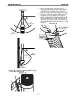
Page 23: ...out of the friction tube See Figure A 20 FIGURE A 20 2 Mount the telescoping arm mounting bracket A to the wall Standard mounting height is 63 1600mm from the work table to the center of the bracket R...

Page 24: ...h the arm seal bands 5 Fold back 2 3 of both arm seal bands Remove the wrap of the flexible hose Place the flexible hose over both arm sections To secure the hose at least one metal rings of the hose...

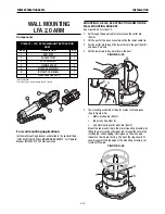
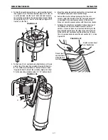
Page 25: ...tem B and bend it around 4 Cut the lower cable tie and let down the post FIGURE A 25 2 The mounting assembly of the arm comes in three pieces See to Figure A 26 Metal rotating rod Item A red plastic r...

Page 26: ...and nuts FIGURE A 28 5 Mount the spring bracket and position the arm seal band and the flexible hose around the connection flange 6 Remove the plastic and tape packaging from the arm sections Adjust...

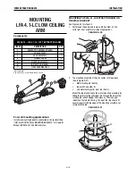
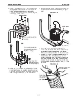
Page 27: ...0 2 The mounting assembly of the arm comes in three pieces See to Figure A 31 Metal rotating rod Item A red plastic ring Item B and metal spring collar pivot rod Item C Mount the red plastic ring to t...

Page 28: ...3 6 Remove the plastic and tape packaging from the arm sections Adjust the friction of the arm and hood movement as described in the maintenance section of this manual When set seal all hose connectio...

Page 29: ...h covers open or filter removed Keep away from moving parts ONLY QUALIFIED PERSONNEL SHOULD INSTALL USE OR SERVICE THIS EQUIPMENT This installation section describes installation of a K1671 1 7 ft Ext...

Page 30: ...en the upper and lower part of the wall bracket E and hold it in place b Insert the locking pin B through the upper part of the wall bracket and subsequently through both plastic hinge joints of the c...

Page 31: ...plied to extension piece M nylon washer J steel washer K 7 Secure bolt with selflocking nut 3 4 L 8 Both tubes contain a supply wire each attached with a tie wrap Cut both tie wraps 9 Fold back 2 3 of...

Page 32: ...the hose at least one metal ring of the hose should be applied over the ridges at the tube 19 Fold back the rubber seal and place it over the hose The rubber seal should cover 0 5 to 1 inch of the tu...

Page 33: ...knob s The throttle valve is mostly used when several extraction arms are integrated in a line installation in such configurations closing the throttle valve prevents the loss of costly heated air NO...

Page 34: ...rox 50 seconds after finishing welding refer to the corresponding manual Fire hazard Never use the product for extracting inflammable glowing or burning particles or solid liquids Never use the produc...

Page 35: ...69 4 LAMP KIT WITH ARC SENSOR SF2400 FAN Mounted in the lamp housing the arc sensor turns the fan on when sensing the arc flash and turns off 50 seconds after the arc extin guishes Hood mounted switch...

Page 36: ...al Protective Equipment PPE to avoid injury This also applies for persons who enter the work area Always use tools materials lubricants and service techniques which have been approved by the manufactu...

Page 37: ...NON AGGRESSIVE DETERGENT X FLEXIBLE HOSES CHECK FOR CRACKS OR DAMAGES REPLACE IF NECESSARY X INSIDE ARM CHECK AND CLEAN THOROUGHLY X ARM MOVEMENT CHECK HORIZONTAL VERTICAL AND DIAGONAL ARM MOVEMENT IF...

Page 38: ...he extraction hood falls on its own Pull back the arm band seal and flexible hose Push the corrugated cover Item A Figure F 5 back to expose the wrist joint Use a wrench and socket and ratchet to adju...

Page 39: ...nsion arM aDjUstMent Adjust the 4 bolts Fig F 8 Item B at the base Fig F 8 Item A to squeeze the friction blocks around the pivot pin see Figure F 8 FUME EXTRACTION ARMS 17 13 A B FIGURE F 7 ARM ADJUS...

Page 40: ...nuts on the u clamp Feigner F 9 Item A with a socket and ratchet To adjust the friction setting for front to back movement adjust the friction clamp bolts Figure F 9 Item B on the rotating hinge with...

Page 41: ...s possible symptoms that the machine may exhibit Find the listing that best describes the symp tom that the machine is exhibiting Step 2 POSSIBLE CAUSE The second column labeled POSSIBLE CAUSE lists t...

Page 42: ...JUSTING MECHANISM EXTRACTION HOOD NOT IN BALANCE TOO MUCH OR NOT ENOUGH FRICTION AGEING ADJUST THE FRICTION USING THE BOLT AND NUT ON THE PLASTIC PLUG EXTRACTION CAPACITY INSUFFICIENT THROTTLE VALVE C...

Page 43: ...ii THIS PAGE INTENTIONALLY LEFT BLANK...

Page 44: ...SEAL BAND 6 7 9SCF000063 5 16 18X2 00HHCS 2 8 9SCF000016 1 4 20X1 75HHCS 1 9 9SS9262 98 PLAIN WASHER 2 10 9ST9187 16 1 4 20 HLN 1 11 9ST9187 15 5 16 18HLN SS 10 12 9SCF000075 5 16 18X1 75HHCS 2 13 9S...

Page 45: ...P 960 C jpg LFA 3 1 WITH FLANGE K1655 8 General Assembly LFA 3 1 WITH FLANGE K1655 8 2 9 10 5 6 4 16 6 1 7 18 6 15 11 6 4 3 14 12 13 6 17 6 9 8...

Page 46: ...SEAL BAND 6 7 9SCF000063 5 16 18X2 00HHCS 2 8 9SCF000016 1 4 20X1 75HHCS 1 9 9SS9262 98 PLAIN WASHER 2 10 9ST9187 16 1 4 20 HLN 1 11 9ST9187 15 5 16 18HLN SS 10 12 9SCF000075 5 16 18X1 75HHCS 2 13 9SC...

Page 47: ...P 961 C jpg LFA 4 1 WITH FLANGE K1655 9 General Assembly LFA 4 1 WITH FLANGE K1655 9 2 9 10 5 6 4 16 6 1 7 6 4 6 17 6 12 14 3 11 15 6 13 18 9 8 18 17...

Page 48: ...IST HINGE ASSEM 1 7 9SCF000016 1 4 20X1 75HHCS 1 8 9SS31226 24 COVER FLEX WRIST HINGE 1 9 9SS31226 320 ROTAHOOD RND RED ASSEM 1 10 9ST9187 16 1 4 20 HLN 3 11 9SS31256 4 1 12 9SS31256 5 1 13 9SS9262 98...

Page 49: ...P 962 C jpg LTA 2 0 T FLEX K1655 10 General Assembly LTA 2 0 T FLEX K1655 10 1 2 10 4 5 3 4 6 10 9 7 13 12 3 4 8 9 11 14 15...

Page 50: ...SPRING HOSE HANG 1 7 9SFC0840101030 ARM SEAL BAND 4 8 9SCF000063 5 16 18X2 00HHCS 2 9 9SCF000187 5 16 18X2 50HHCS 6 10 9SCF000016 1 4 20X1 75HHCS 1 11 9ST9187 15 5 16 18HLN SS 10 12 9ST9187 16 1 4 20...

Page 51: ...P 963 C jpg LFA 2 0 FLEXIBLE ARM K1655 12 General Assembly LFA 2 0 FLEXIBLE ARM K1655 12 1 2 13 13 12 7 14 3 5 7 4 7 8 6 15 7 9 10 11 11 16 17...

Page 52: ...7 9SFC0840101030 ARM SEAL BAND 6 8 9SCF000187 5 16 18X2 50HHCS 4 9 9ST8833 4 HEX HD CAP SCREW 3 10 9SCF000063 5 16 18X2 00HHCS 2 11 9SCF000016 1 4 20X1 75HHCS 1 12 9ST9187 16 1 4 20 HLN 1 13 9ST9187 1...

Page 53: ...P 964 C jpg LFA 4 1 FLEXIBLE ARM K1655 13 General Assembly LFA 4 1 FLEXIBLE ARM K1655 13 1 2 3 4 5 7 7 7 7 10 13 17 8 16 9 13 15 12 14 13 19 11 6 18 19...

Page 54: ...PE WHEEL 1 18 9SFC0711010150 SIDE PLATE LTA2 CW 2 19 9SS31226 96 COLLAR HINGE PIVOT 1 20 9SFC0703090160 LTA 2 0 CW WIRE SPRING 1 21 9SFC0711010360 LOCKING PLATE 1 22 9SFC0342000070 GROMMET CLOSED 1 23...

Page 55: ...C jpg LTA 2 0 TELESCOPIC ARM K1655 14 General Assembly LTA 2 0 TELESCOPIC ARM K1655 14 1 14 3 4 5 6 8 9 10 11 12 13 2 15 15 16 31 15 28 21 22 18 17 29 20 27 30 23 34 35 24 19 10 24 26 25 26 7 30 30 3...

Page 56: ...HINGE 1 5 9SFC0840101030 ARM SEAL BAND 5 6 9SCF000063 5 16 18X2 00HHCS 2 7 9SCF000016 1 4 20X1 75HHCS 1 8 9SS9262 98 PLAIN WASHER 2 9 9ST9187 16 1 4 20 HLN 1 10 9ST9187 15 5 16 18HLN SS 2 11 9SS31256...

Page 57: ...P 966 C jpg LFA 3 1 K2633 5 General Assembly LFA 3 1 K2633 5 1 3 3 4 5 5 5 5 6 10 12 11 9 8 2 7 8 14 13...

Page 58: ...T HINGE 1 5 9SFC0840101030 ARM SEAL BAND 5 6 9SCF000063 5 16 18X2 00HHCS 2 7 9SCF000016 1 4 20X1 75HHCS 1 8 9SS9262 98 PLAIN WASHER 2 9 9ST9187 16 1 4 20 HLN 1 10 9ST9187 15 5 16 18HLN SS 2 11 9SS3125...

Page 59: ...P 967 C jpg General Assembly 4 LFA 3 1 K2633 6 Printed 02 11 2016 at 10 26 47 Produced by Enigma...

Page 60: ...HINGE 1 5 9SFC0840101030 ARM SEAL BAND 5 6 9SCF000063 5 16 18X2 00HHCS 2 7 9SCF000016 1 4 20X1 75HHCS 1 8 9SS9262 98 PLAIN WASHER 2 9 9ST9187 16 1 4 20 HLN 1 10 9ST9187 15 5 16 18HLN SS 2 11 9SS31256...

Page 61: ...P 968 C jpg LFA 4 1 K2633 7 General Assembly LFA 4 1 K2633 7 14 13...

Page 62: ...HINGE 1 5 9SFC0840101030 ARM SEAL BAND 5 6 9SCF000063 5 16 18X2 00HHCS 2 7 9SCF000016 1 4 20X1 75HHCS 1 8 9SS9262 98 PLAIN WASHER 2 9 9ST9187 16 1 4 20 HLN 1 10 9ST9187 15 5 16 18HLN SS 2 11 9SS31256...

Page 63: ...P 969 C jpg LFA 4 1 K2633 8 General Assembly LFA 4 1 K2633 8 14 13...

Page 64: ...ii THIS PAGE INTENTIONALLY LEFT BLANK...

Page 65: ...ii THIS PAGE INTENTIONALLY LEFT BLANK...
Page 66: ...parts or electrode with skin or wet clothing l Insulate yourself from work and ground l No toque las partes o los electrodos bajo carga con la piel o ropa moja da l Aislese del trabajo y de la tierra...

Page 67: ...d Entl ftung des Arbeitsplatzes l Mantenha seu rosto da fuma a l Use ventila o e exhaust o para remover fumo da zona respirat ria l Turn power off before servicing l Desconectar el cable de ali mentac...

Page 68: ...dvice once it has been given nor does the provision of information or advice create expand or alter any warranty with respect to the sale of our products Lincoln Electric is a responsive manufacturer...

Reviews: