A-10
INSTALLATION
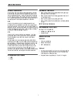
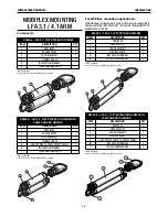
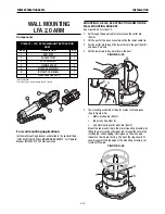
FUME EXTRACTION ARMS
Electrical Connection for Lamp and Arc Sensor
The K2633-6 or K2633-8 LFA 3.1/4.1 Mobile Automatic extraction
arm contains an integrated Lamp & Arc Sensor Kit.
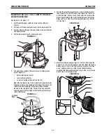
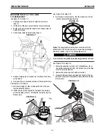
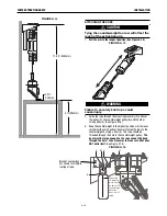
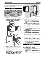
The supply cable inside the base swivel mount
should hang down vertically. Do not remove the
wire bridge.
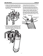
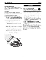
See Figure A.11 for steps 4-7
4. Remove the wire bridge from the supply cable inside the base
swivel mount.
5. Connect the supply cables of the Mobiflex 200 or 200 HE Base
Unit and the extraction arm.
NOTE: If you are using an older Mobiflex 200-M with an older
connection on the supply side, use the supplied adapter cable
S31224-62 in the loose hardware kit.
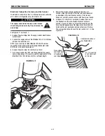
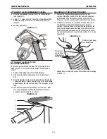
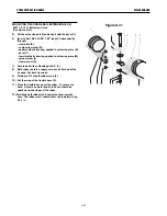
6. Remove the yellow tape from both arm sections.
7. Turn the extraction arm 359° and check whether the supply
cable is long enough. If necessary, pull the supply cable of the
Mobiflex 200 or 200 HE Base Unit to a sufficient length.
FIGURE A.11
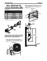
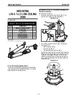
8. Remove the plastic and tape packaging from the arm
sections. Adjust the friction of the arm and hood movement
as described in the maintenance section of this manual.
When set, seal all hose connections with the arm seal bands.
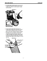
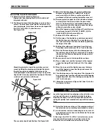
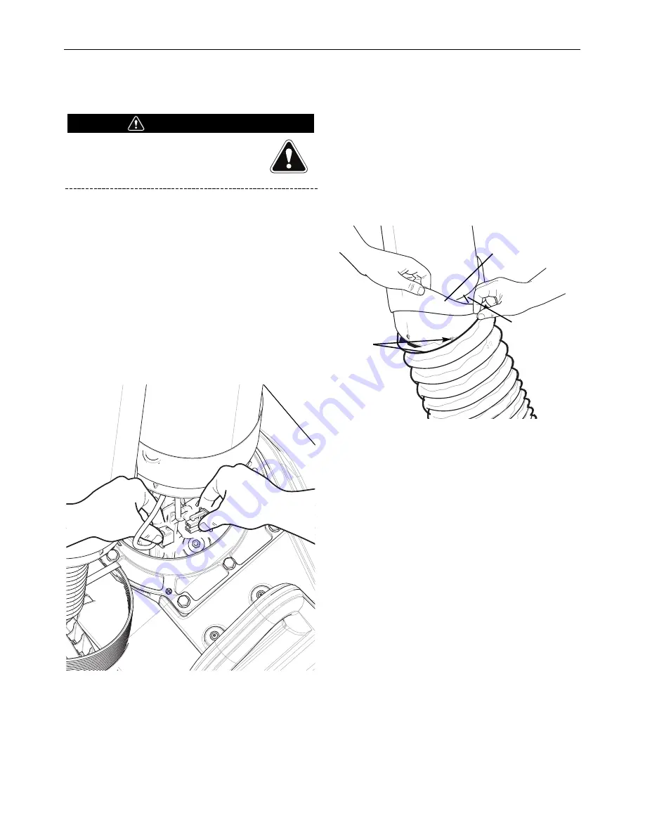
9. Fold back 2/3 of both arm seal bands. Remove the wrap of
the flexible hose. Place the flexible hose over both arm
sections. To secure the hose, at least one metal rings of the
hose should be applied over the ridges at each arm section.
Fold back the arm seal bands and place them over the hose.
The arm seal band should cover the arm section 0.5-1 in. See
Figure A.12
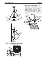
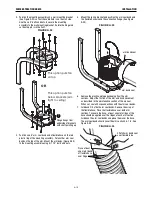
FIGURE A.12
ATTENTION
0.5 - 1in. overlap
of arm band seal
on the arm
Place at least
one metal band
of flexible hose
over ridge
Stretch arm band seal
over flexible tube
Summary of Contents for K1655-10-LTA 2.0
Page 43: ...ii THIS PAGE INTENTIONALLY LEFT BLANK...
Page 61: ...P 968 C jpg LFA 4 1 K2633 7 General Assembly LFA 4 1 K2633 7 14 13...
Page 63: ...P 969 C jpg LFA 4 1 K2633 8 General Assembly LFA 4 1 K2633 8 14 13...
Page 64: ...ii THIS PAGE INTENTIONALLY LEFT BLANK...


