A-17
INSTALLATION
FUME EXTRACTION ARMS
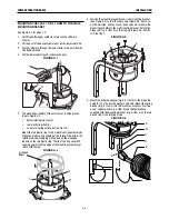
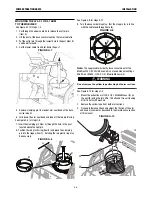
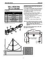
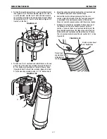
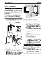
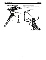
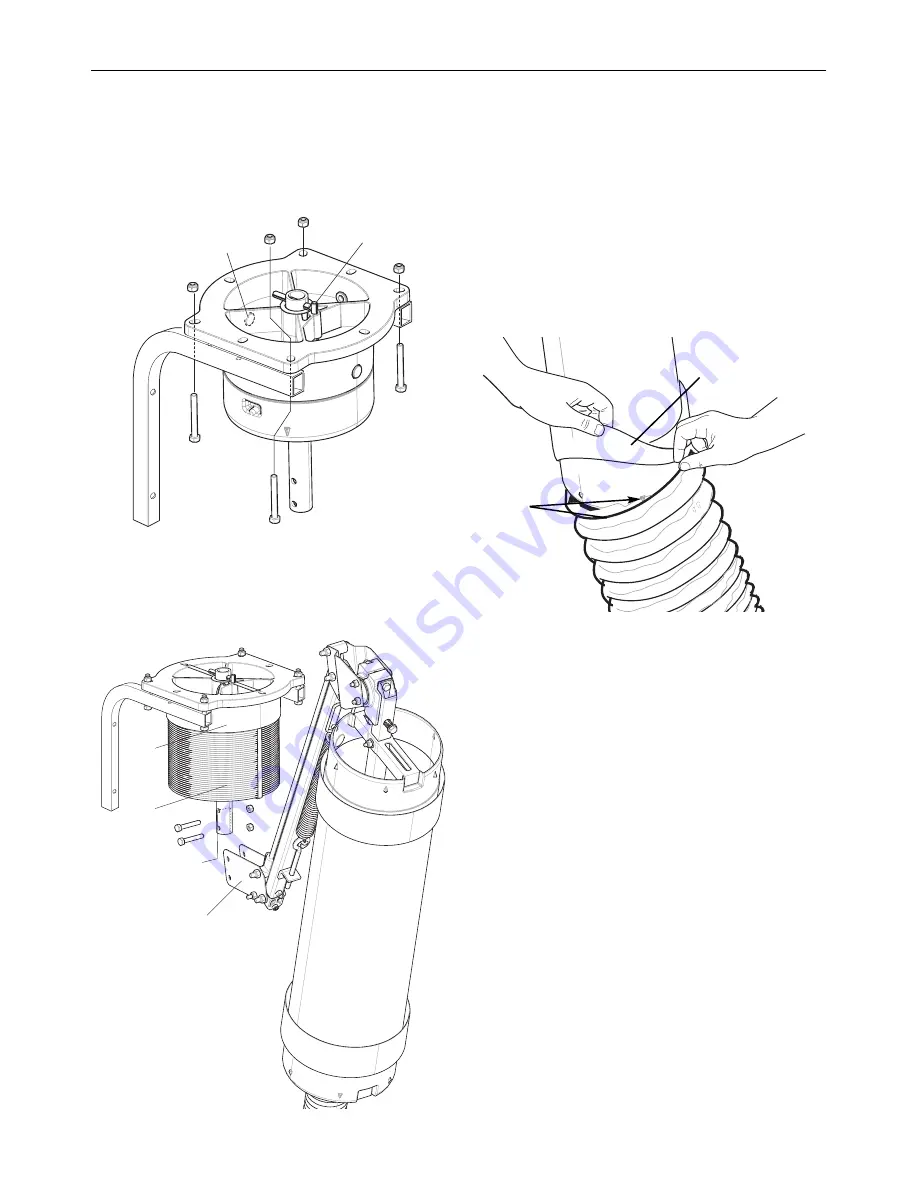
3. Position the mounting assembly on a wall mounting bracket
(See Figure A.27) so that the cable hole (Figure A.27, Item A)
is on the wall side. Use the four 3” bolts and nuts to secure
the mounting assembly to the wall mounting bracket. Rotate
the hinge rod (Fig. A.27, Item D) so the stop pin (Figure A.27,
Item B) is in the front.
FIGURE A.27
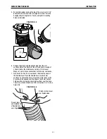
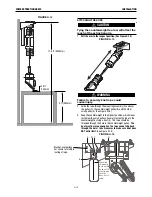
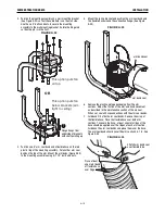
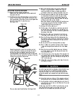
4. Position one 8” arm seal band and a flexible hose on the red
plastic ring of the mounting assembly (Figure A.28 Item A &
B). Put another arm seal band on the top of the arm Body
(Figure A.28 Item C). Mount the arm body (Figure A.28, Item
D) to the mounting assembly using (2) 1.75” bolts and nuts.
FIGURE A.28
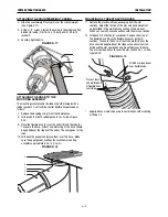
5. Mount the spring bracket and position the arm seal band and
the flexible hose around the connection flange.
6. Remove the plastic and tape packaging from the arm
sections. Adjust the friction of the arm and hood movement
as described in the maintenance section of this manual.
When set, seal all hose connections with the arm seal bands.
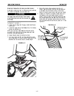
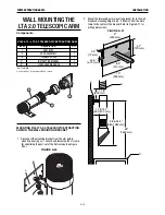
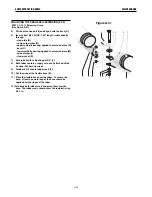
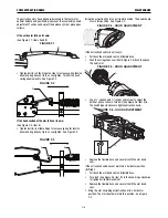
7. Fold back 2/3 of both arm seal bands. Remove the wrap of
the flexible hose. Place the flexible hose over both arm
sections. To secure the hose, at least one metal rings of the
hose should be applied over the ridges at each arm section.
Fold back the arm seal bands and place them over the hose.
The arm seal band should cover the arm section 0.5-1 in. See
Figure A.29
FIGURE A.29
A
B
A
B
D
C
Place at least
one metal band
of flexible hose
over ridge
Stretch arm band seal
over flexible tube
Summary of Contents for K1655-10-LTA 2.0
Page 43: ...ii THIS PAGE INTENTIONALLY LEFT BLANK...
Page 61: ...P 968 C jpg LFA 4 1 K2633 7 General Assembly LFA 4 1 K2633 7 14 13...
Page 63: ...P 969 C jpg LFA 4 1 K2633 8 General Assembly LFA 4 1 K2633 8 14 13...
Page 64: ...ii THIS PAGE INTENTIONALLY LEFT BLANK...

