A-21
INSTALLATION
FUME EXTRACTION ARMS
MoUntinG tHe Wall bracKet
Before you install the wall bracket, make sure that the wall
is strong enough [minimum wall thickness: 8 in. (200 mm)].
Locate any gas and water pipes and electric cables before
drilling any holes.
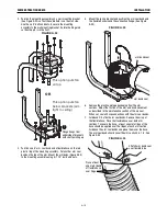
Leave the tape and plastic packaging on the extraction arm
sections until the arm is completely installed (including
mounting the hood). The arm is spring-balanced to
compensate for the weight of the hood and will spring out
quickly if it is not mounted securely, with the hood in place.
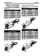
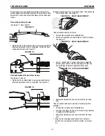
1.)
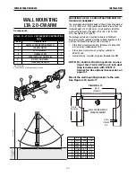
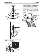
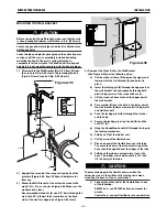
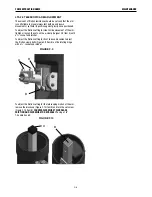
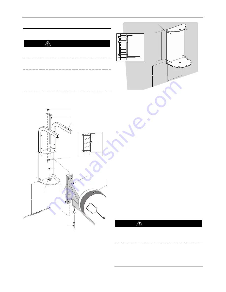
Disassemble the Wall Bracket (Fig. A.35, Item E) from
the crane rail (Fig. A.35, Item F) by removing the bolt
(Fig. A.35 Item A) and nut (Fig. A.35, Item D).
2.)
Support the far end of the crane rail, and pull out the
pivot pin (Figure A.35, Item B). Save all hardware for
later use.
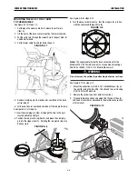
3.)
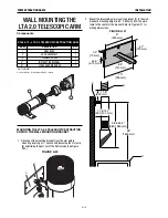
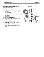
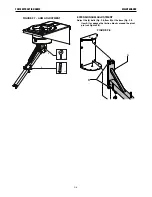
Mount the Wall Bracket of the extension crane to the
wall at 8 ft., 8 in. as shown in Figure A.36 Make sure the
wall bracket is level.
Recommended method is (4) min. 3/8” bolts through the
wall, with 0.2 in. (5mm) thick steel plate on the back
side of the wall for support (see Figure A.36 Inset).
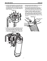
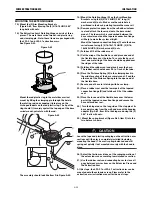
4.) Remount the Crane Rail to the Wall Bracket
(See Figure A.35) per the following steps:
a)
Put the crane rail base (F) between the upper and
lower part of the wall bracket (E) and hold it in
place.
b)
Insert the locking pin (B) through the upper part of
the wall bracket and subsequently through both
plastic hinge joints of the crane rail base (I).
c)
Lift the crane rail base to touch the upper part of
the wall bracket.
d)
Put a washer (H) over the hole in the lower part of
the wall bracket (between lower plastic hinge joint
and wall bracket).
e)
Push the locking pin further through the washer
and the hole.
f)
Secure the locking pin using the bolt (A) and the
nut 5/16” (D).
g)
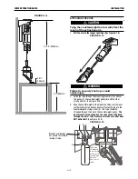
Hang the HandyStop handle (G) through the loop in
the locking mechanism.
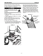
h)
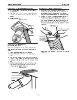
Fold back 2/3 of the rubber seal.
i)
Cut the wrap of the flexible hose.
j)
Place one end of the flexible hose over the tube.
To secure the hose, at least one metal ring of the
hose should be applied over the ridges at the tube.
k)
Fold back the rubber seal and place it over the
hose. The rubber seal should cover 0.5 to 1 inch
(13 to 25 mm) of the tube.
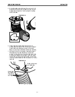
To prevent damage to the flexible hose, position the
extension crane in the middle of its turning circle when
mounting the hose to a fan or central duct.
l)
Connect the other end of the flexible hose to one
of the following:
SF4200 Fan – see SF4200 instruction manual for
details.
Central Fan – connect flexible hose to central duct.
CAUTION
CAUTION
8.8 ft.
E
C
F
B
A
D
I
H
E
J
K
G
Figure A.35
104"
(2650 mm)
3/8"
3/8"
8" (200 mm)
13
9
/
16
”
9
1
/
8
”
3
/
8
” Hole (TYP-4)
Figure A.36
Summary of Contents for K1655-10-LTA 2.0
Page 43: ...ii THIS PAGE INTENTIONALLY LEFT BLANK...
Page 61: ...P 968 C jpg LFA 4 1 K2633 7 General Assembly LFA 4 1 K2633 7 14 13...
Page 63: ...P 969 C jpg LFA 4 1 K2633 8 General Assembly LFA 4 1 K2633 8 14 13...
Page 64: ...ii THIS PAGE INTENTIONALLY LEFT BLANK...

