
4
INSTALLATION
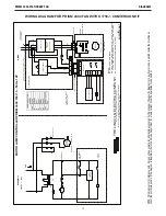
PRISM 2400 STATIONARY FAN
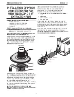
INSTALLATION OF PRISM
2400 STATIONARY FAN WITH
FLEXIBLE 10 FT OR 13 FT
EXTRACTION ARM
K1656-9 Prism 2400 Stationary Fan Includes:
• Prism 2400 Stationary Fan
• (2) Bolts, M8x1.25, about 0.75” (20mm) long
• (2) Bolts, M8x1.25, about 2.5” (65mm) long
• (4) Washers, M8
K1655-8 Flexible 10 FT or K1655-9 Flexible 13 FT Arm
includes:
• Assembled arm, 2 sections
• Flexible hose, (2) 8” Rubber seals for hood hinge
• Hood assembly
• (2) Bolts, M8x1.25, about 1.75” (45mm) long
• (2) Nuts, M8 self-locking
• Hose running guard
• Clamping pin for red plastic ring
• Metal rotating hinge
• Red plastic ring
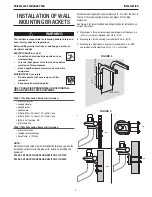
Install mounting brackets as detailed in the section titled
“INSTALLATION OF WALL MOUNTING BRACKETS”
Mounting the Extraction Arm
Leave the tape and plastic packaging on the extraction arm
sections until the arm is completely installed (including
mounting the hood).
The arm is spring-balanced to compensate for
the weight of the hood and will spring out quickly if it is not mounted
securely, with the hood in place.
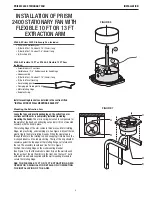
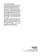
The rotating hinge of the arm comes in three pieces: Metal rotating
hinge, red plastic ring, and clamping pin. See Figure 6. Mount the red
plastic ring to the metal rotating hinge by fitting the clamping pin
through the hole in the rotating rod, and snapping it into place on the
U-shaped indents on the red plastic ring. The lip of the ring should fit
securely against the top edge of the rotating flange, yet rotate with
the rod. The assembly should look like Part C in Figure 7.
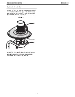
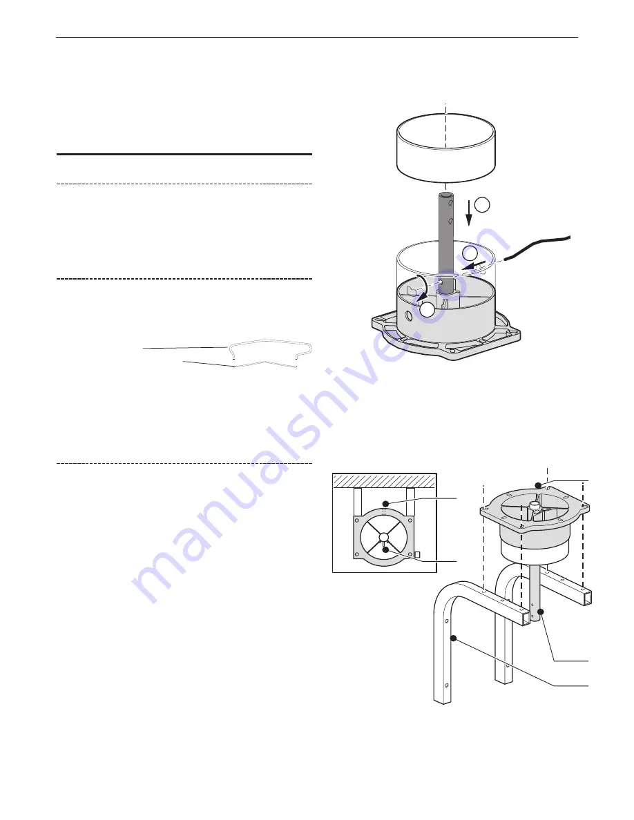
Position the rotating hinge on the wall mounting bracket
(See Figure 7) so that the cable hole (Item A) is on the wall side and
the long side of the pin (Item B) is in the front. Use the four 3” bolts
with washers and nuts supplied withthe wall mounting brackets to
secure the rotating hinge.
SEE THE FLEXIBLE 10 FT OR 13 FT EXTRACTION ARMS
OPERATOR’S MANUAL FOR DETAILS ON COMPLETING
THE INSTALLATION OF THE ARM.
FIGURE 6
2
1
3
FIGURE 7
D
E
C
B
A


