
12
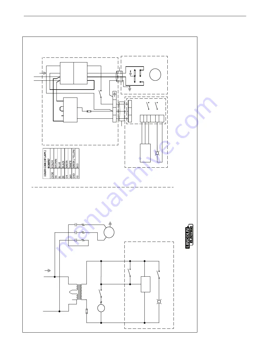
DIAGRAMS
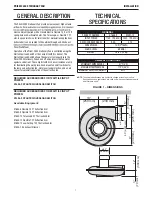
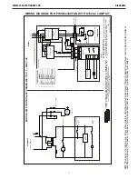
PRISM 2400 STATIONARY FAN
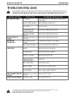
NOTE: This diagram is for reference only. It may not be accurate for all machines covered by this manual. The specific diag
ram for a particular code is pasted inside the machine on
one of the enclosure panels. If the diagram is illegible, write to the Service Department for a replacement. Give the equipme
nt code number.
S
al
es
and
S
er
vi
ce
th
rough
S
ub
si
di
ar
ie
s
and
D
is
tri
bu
to
rs
W
or
ld
w
id
e
C
le
ve
land,
O
hi
o
44
117
-1199
U
.S
.A
.
THE LIN
C
OLN
ELE
CTR
IC
C
O
M
PAN
Y
W
or
ld
's
Lea
de
r i
n
W
el
di
ng
a
nd
C
ut
ting
P
rodu
ct
s
S312
25-
25
PR
IN
T
B
230V
A
C
, 1~
,5
0H
z
N
2
24
V
2A
1
A
1
A
C
C
O
L
A
2
FA
N
O
N
/O
FF
N
24
V
FA
N
M
A
NUA
L
O
N
/O
FF
A
R
C
S
E
N
S
O
R
FL
O
O
D
LI
G
H
T
C
O
L
S
E
T
TO
5
.7
5A
BK
BK
FA
N
M
O
TO
R
230
VAC
, 1~
,5
0Hz
, 1
H
P
L
N
S
1
S
2
S
3
SC
H
EMA
TI
C
1
3
4
5
6
10
G
N
D
C
O
N
TR
O
L
B
O
X
L
GND
CONNECT
GND
TO
TE
RM
INA
L
N
205
204
B
L1
L2
L3
A
1
13
CON
TA
C
TOR
OV
E
R
LOA
D
RE
LA
Y
S
ET
A
T
5.
75
A
T1
T2
T3
A
2
1
3
TRA
NS
FO
R
M
E
R
N
24
V
2A
W
H
B
K
R
D
3
CONDU
C
TO
R
CAB
LE
,
PRO
V
ID
ED
2
0A
W
G
A
RC
S
E
NS
OR
W
H
B
L
RD
B
K
B
K
W
H
CONN-
P
CB
Y
E
/GN
MOT
OR
GND
FA
N
MO
TO
R
S
1
S
2
S
3
STA
R
T
C
A
P
A
C
ITO
R
23
0V
A
C,
1
~,
50
H
z,
1H
P
201
20
2
202
201
4
5
207
206
NA
205
20
3
20
9
20
3
207
204
A
204B
209
W
IR
IN
G
3
C
ORE
16
A
W
G
CA
B
LE
20
AW
G
3
CORE
CA
B
LE
N
L
N
L
Z2
U
2
V
2
U1
V
1
Z1
B
K
RD
2
6
10
N
B
.
N
B
.
D
ISC
O
N
N
EC
TI
N
G
MEA
N
S
AN
D
BR
A
NC
H
C
IRC
U
IT
PR
O
TEC
TIO
N
SH
AL
L
BE
P
R
O
VI
D
ED
B
Y
T
H
E
IN
ST
A
LL
ER
20
8
M
O
TO
R
L
AM
P
CON
TRO
LL
ER
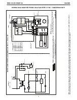
PRISM
2400
, 230
V,
1~
, 50H
z,
1H
P
N
O
TE
S
:
N
A.
M
O
UNT
IN
G
ON
D
IN
R
AI
L
N
B.
F
IE
LD
W
IR
ING
S
H
A
LL
U
S
E
UL
R
A
TE
D
3C
M
IN
16
A
W
G
C
A
B
LE
W
IT
H
O
U
TE
R
D
IA
BET
W
EE
N
0
.2
7
TO
0
.5
1
(7
M
M
TO
1
3M
M
)
N
C
. 201
,2
02
,20
8 S
H
A
LL
BE B
LA
C
K A
ND
14
A
W
G
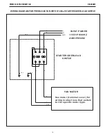
WIRING DIAGRAM FOR PRISM 2400 FAN WITH K1750-1 CONVERSION KIT


