3
INSTALLATION
PRISM 2400 STATIONARY FAN
INSTALLATION OF WALL
MOUNTING BRACKETS
The installer is responsible for following Federal, State and
Local safety codes and regulations.
Before drilling, verify locations of existing gas, water, or
electrical conduits.
ELECTRIC SHOCK can kill.
•
Do not touch electrically live parts such as
internal wiring.
•
Turn the input power off at the fuse box before
working on this equipment.
•
Have a qualified person install and service this
equipment.
MOVING PARTS can injure.
•
Do not operate with covers open or filter
removed.
•
Keep away from moving parts.
ONLY QUALIFIED PERSONNEL SHOULD INSTALL,
USE OR SERVICE THIS EQUIPMENT.
K1657-1 Wall Mounting Bracket kit includes:
• (2) Bracket pieces
• Hanging Adapter
• Spring Bracket
• Flexible Hose
• (2) Bolts, M8x1.25, about 1.75” (45mm) long
• (4) Bolts, M8x1.25, about 3.00” (75mm) long
• (6) Nuts, Self-Locking, M8
• (6) Washers, M8
K1657-2 Wall Mounting Bracket kit includes:
• (2) Bracket pieces
• Tapered connection flange
• Hose Clamp, 8” (203mm)
NOTE:
Starter/Overload Switch must be installed with this package. See the
installation section later in this manual for details on installing this
equipment.
K1494-2 STARTER/OVERLOAD SWITCH FOR 120V
K1494-3 STARTER/OVERLOAD SWITCH FOR 230V
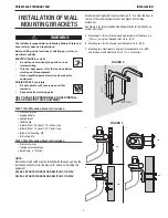
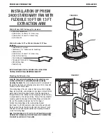
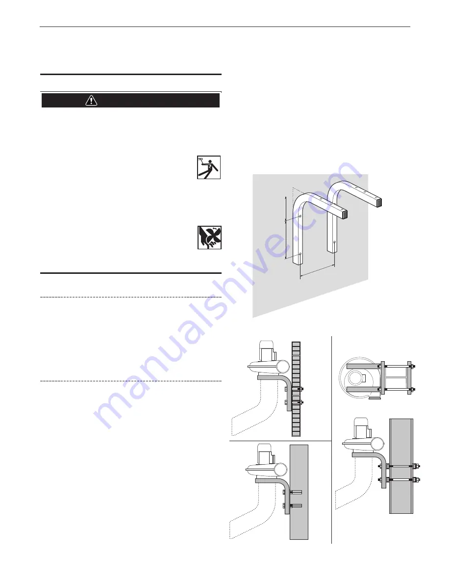
Standard mounting height is approximately 8 ft., 2 in. from the floor to
the top of the wall mounting bracket. See Figure 4 for drilling
dimensions.
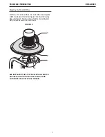
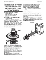
See Figure 5 for recommended mounting methods for installation on
various wall types.
A. Mounting on a thin wall (recommended minimum wall thickness 5 in.
(100 mm), using four threaded rods, 3/8 in. (M10).
B. Mounting on a thick wall using four cotter bolts 3/8 in. (M10).
C. Mounting on a steel I-beam using four threaded rods 3/8 in. (M10)
and two box-profile stabilizers (1x1x0.1 in., 30x30x3mm).
WARNING
FIGURE 4
9" (230 mm)
8.3"
(210 mm)
6.3" (160 mm)
FIGURE 5
A
C
B
3/8"
3/8"
3/8"
3/8"


