

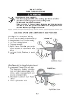
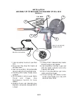


LOCATING SPOOL GUN COMPONENTS AND FEATURES
(
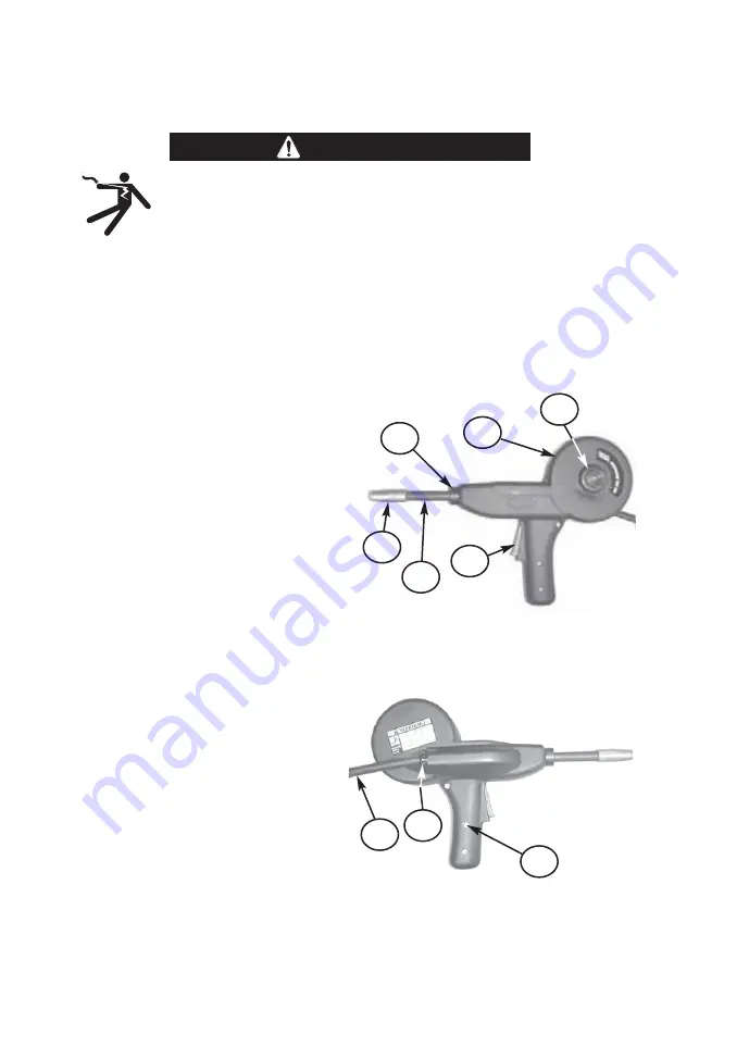
See Figure 1.A
f
or Items 1 thru 6
)
1.
G
as Cone Assembl
y
and Contact Ti
p
.
2. Straightened
G
un Tube Assembl
y
.
3
. 1/4-Turn Locking Collar.
4. Trigger Assembl
y
.
5. S
p
ool Cover: Provides eas
y
, wide-
o
p
en access to s
p
ool and wire
drive.
6. Locking Knob: Ca
p
tive in s
p
ool
cover.
(
See Figure A.2
f
or these
f
ollowing items
)
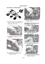
7. Integrated Single-Piece Cable:
The
M
agnum
®
design
p
rovides
neat and clean a
pp
earance; sim-
p
li
f
ies cable management and
reduces entanglements.
8. Standard Durable Strain
R
elie
f
Clam
p
.
9. Three Ca
p
tive Hex
N
uts.
FIGURE A.1
Le
f
t Side View
1
4
3
5
5
2
FIGURE A.2
R
ight Side View
7
8
9
A-2
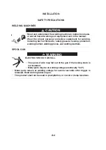
INSTALLATION
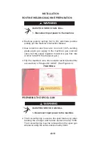
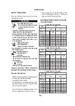
SAFETY PRECAUTIONS
ELECTRIC SHOCK CAN KILL.
• Turn the input power OFF at the welding power source before
installation or changing drive rolls and/or guides.
• Do not touch electrically live parts.
• When inching with the gun trigger, electrode and drive mechanism
are "hot" to work and ground and could remain energized several
seconds after the gun trigger is released.
-----------------------------------------------------------------------------------------------------
WARNING
Summary of Contents for K2532-1
Page 3: ......
Page 4: ......
Page 22: ...NOTES MAGNUM 100SG...
Page 36: ...MAGNUM 100SG NOTES...
Page 41: ......
Page 58: ...NOTAS MAGNUM 100SG...
Page 72: ...MAGNUM 100SG NOTES NOTAS...
Page 75: ......
Page 76: ......
Page 94: ...NOTES MAGNUM 100SG...
Page 108: ...MAGNUM 100SG NOTES MAGNUM 100SG NOTES...
Page 109: ...NOTES NOTAS MAGNUM 100SG...
Page 115: ...NOTES NOTAS MAGNUM 100SG...


