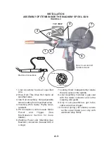

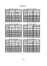


OPERATION
B-3
A
f
ter choosing the
p
ro
p
er welding wire
f
or
y
our a
pp
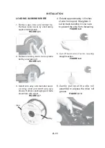
lication, load the aluminum
wire, connect the gun and cable to the
welding machine.
(
See Installation
Section
)
.
WELDING PROCEDURES
1.
R
ead and understand Arc Welding Sa
f
et
y
Precautions located throughout this manual
and the Welding
M
achine
ʼ
s Instruction
M
anual.
Also
f
or hel
pf
ul hints in welding see
(
LTW1
)
the
Learn to Weld manual which is su
pp
lied with
the welding machine.
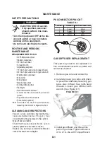
2. Obtain and use the
p
ro
p
er
p
ersonal
p
rotective
e
q
ui
p
ment
f
or welding. Connect the WO
R
K
(
welding ground
)
cable
(
-
)
to
p
iece
(
s
)
being
welded.
M
ake sure gas hose
f
rom c
y
linder
ʼ
s
regulator is connected to welder
ʼ
s gas I
N
LET.
O
p
en c
y
linder
ʼ
s gas valve.
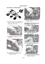
3
. Connect in
p
ut
p
ower to the machine.
4. Turn the machine
ʼ
s
p
ower switch to "on". Set
wire s
p
eed and voltage ta
p
settings to tables
which are
p
rovided in the beginning o
f
this
section.
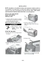
5. Fli
p
toggle selector switch inside o
f
machine to
"
M
agnum® 100S
G
"
p
osition. Press and hold
trigger
f
or about 5 seconds to
p
urge hose. Be
sure the
G
as
f
low rate is set to 20 to 50 SCFH
thru the s
p
ool gun.
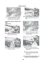
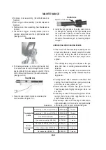
6. Cut o
ff
the aluminum wire so that it extends
about 1/4 inches
f
rom the contact ti
p
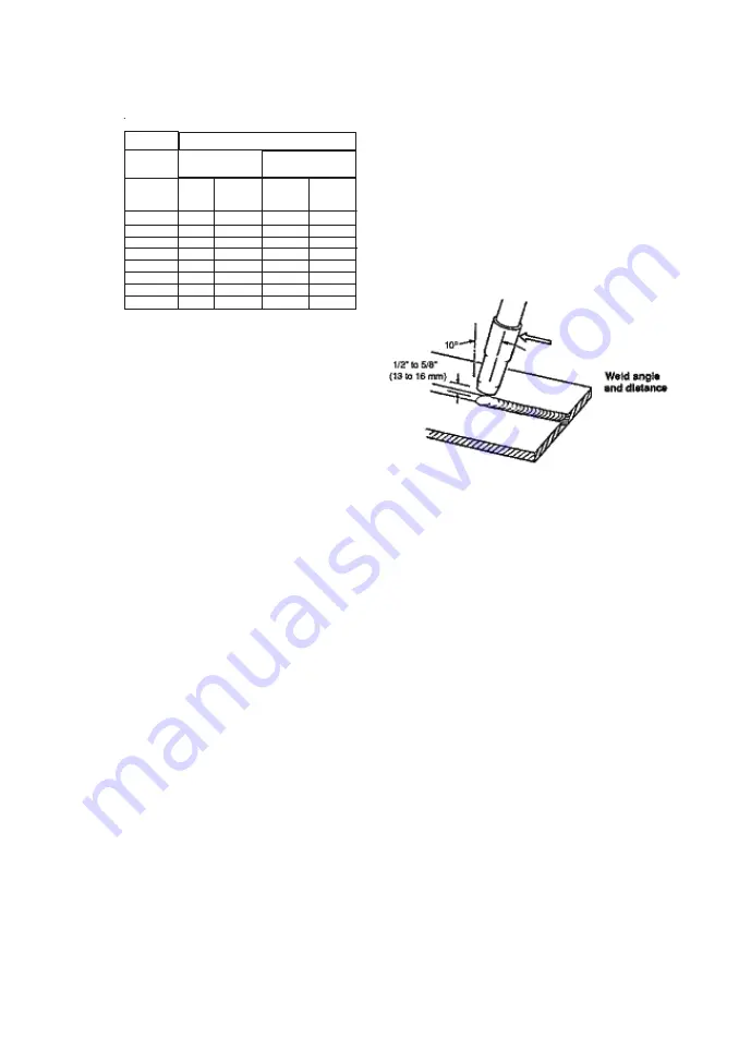
.
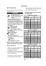
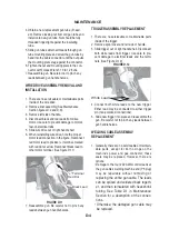
7. CTWD
(
Contact Ti
p
to Work Distance
)
: Position
the gun so that the contact ti
p
is nominall
y
3
/8
inches
f
rom the
j
oint and tilted with a
p
ush
angle toward it. The aluminum wire should not
contact the work
p
iece.
(
See
f
igure B.1
)
FIGURE B.1
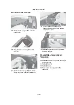
8. Protect the e
y
es and
p
ull the trigger to begin
welding.
9. Ad
j
ust the hand travel s
p
eed o
f
the gun to
achieve a
p
ro
p
er weld. The emerging wire
should sta
y
within the molten
p
uddle and not
overrun it. This s
p
eed also should not be so
slow that either the work
p
iece excessivel
y
melts, or the weld bead becomes excessivel
y
large.
10.
R
elease the trigger to sto
p
welding.
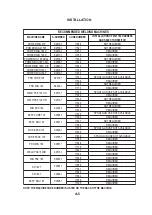
Alloy:
Wire Size:
Weldment
Thickness
22 ga
20 ga
18 ga
16 ga
14 ga
12 ga
10 ga
3/16 in.
Speed
2.5
2.5
4.5
5
6
7
N/A
N/A
Voltage
Tap
A
B
C
D
E
E
N/A
N/A
Speed
2
2
4
4.5
5
5.5
N/A
N/A
Voltage
Tap
A
B
C
D
E
E
N/A
N/A
0.030
0.035
5356
Weld-Pak 125 MACHINE
Alloy:
Wire Size:
Weldment
Thickness
22 ga
20 ga
18 ga
16 ga
14 ga
12 ga
10 ga
3/16 in.
Speed
2.5
2.5
4.5
5
6
7
N/A
N/A
Voltage
Tap
A
B
C
D
E
E
N/A
N/A
Speed
2
2
4
4.5
5
5.5
N/A
N/A
Voltage
Tap
A
B
C
D
E
E
N/A
N/A
0.030
0.035
5356
Weld-Pak 125 MACHINE
Summary of Contents for K2532-1
Page 3: ......
Page 4: ......
Page 22: ...NOTES MAGNUM 100SG...
Page 36: ...MAGNUM 100SG NOTES...
Page 41: ......
Page 58: ...NOTAS MAGNUM 100SG...
Page 72: ...MAGNUM 100SG NOTES NOTAS...
Page 75: ......
Page 76: ......
Page 94: ...NOTES MAGNUM 100SG...
Page 108: ...MAGNUM 100SG NOTES MAGNUM 100SG NOTES...
Page 109: ...NOTES NOTAS MAGNUM 100SG...
Page 115: ...NOTES NOTAS MAGNUM 100SG...


