background image

P

7097


Rev.


01


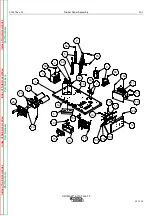
Case Front Assembly


PB

1


OPTIMARC®


AC/DC


350

TP


2017.10


1

2

3

4

5

6

7

8

9

10

11a

11b

11f

11g

15

16

16a

16b

17

18

18a

18b

19

20

11c

11d

11e

11h

15a

16c

17a

19a

20a

9a

5c

Index 

of 

Sub

 Asse

mblies


Index 

of 

Sub

 Asse

mblies


Index 

of 

Sub

 Asse

mblies


Index 

of 

Sub

-As

se

mblies


Part 

Nu

mb

er

Part 

Nu

mb

er

Part 

Nu

mb

er

Part 

Nu

mb

er

Summary of Contents for K60108-1

Page 1: ...incolnelectric com cn Copyright 2019 The Shanghai Lincoln Electric Company Safety Depends on You Lincoln arc welding and cutting equipment is designed and built with safety in mind However your overall safety can be increased by proper installation and thoughtful operation on you part DO NOT INSTALL OPERATE OR REPAIR THIS EQUIPMENT WITHOUT READING THIS MENUAL AND THE SAFETY PRECAUTIONS CONTAINED T...

Page 2: ...rence please record your equipment identification information in the table below Model Name Code Serial Number can be found on the machine rating plate Model Name OPTIMARC AC DC 350 TP Code Serial number K60108 1 Date Where Purchased Authorized dealer s shop Declaration of conformity THE SHANGHAI LINCOLN ELECTRIC COMPANY Designed in conformance with the following norm GB T 15579 1 EN 60974 1 THE S...

Page 3: ...able non flammable screening and or warn them not to watch the arc nor expose themselves to the arc rays or to hot spatter or metal ELECTRIC SHOCK can kill 3 a The electrode and work or ground circuits are electrically hot when the welder is on Do not touch these hot parts with your bare skin or wet clothing Wear dry hole free gloves to insulate hand 3 b Insulate yourself from work and ground usin...

Page 4: ...e equipment in accordance with the national standards and the menufacturer s recommendations WELDING SPARKS can cause fire or explosion 6 a Remove fire hazards from the welding area If this is not possible cover them to prevent the welding sparks from starting a fire Remember that welding sparks and hot materials from welding can easily go through small cracks and openings to adjacent areas Avoid ...

Page 5: ...E FIGURE B 3 B 5 POWER ON B 5 WEIDING MODES B 6 OUTPUT WAVEFORMS B 6 CRATER MODES B 6 PULSE B 7 SETTINGS B 7 MEMORY B 7 WELDING STATUS B 8 WELDING WAVEFORM B 8 WELDING PARAMETERS B 8 CURRENT PARAMETER SETTING B 8 WEIDING CURRENT AND WELDING VOLTAGE B 8 FUNCTION CONFIGURATION STATUS B 8 REMOTE SETTING VALUE B 8 LOCK SCREEN B 9 RECALLED PROCEDURE NUMBER B 9 FAULT IDENTIFICATION B 9 TIG TRIGGER SEQUE...

Page 6: ... 72V 78V 20 4 V 32V SINE TRIANGLE 10A 250A 20 4 V 30V TIG SQUARE 10A 300A 72V 78V 10 4 V 22V SINE TRIANGLE 10A 250A 10 4 V 20V RECOMMENDED INPUT WIRE AND FUSE SIZES Input Voltage Frequency Hz 380V 415V 50 Hz 60 Hz Maximum Input Ampere 30A 24A Maximum Effective Supply Current 19A 15A 60 C Copper Wire in Conduct Sizes 6mm2 Fuse or Breaker Size Super Lag 40A Grounding Conductor Size 4mm2 PHYSICAL DIM...

Page 7: ...RC Connections should be made in accordance with the connection diagram Failure to do so may result in bodily injury or death Open the input box on the rear of the case Use a three phase supply line the three live wires should go through the three holes of the input wire holder and be securely clamped and fixed Connect L1 L2 L3 and ground according to the Input Supply Connection Diagram decal refe...

Page 8: ...HIS MACHINE OR IN THIS MANUAL MMA HIGH FREQUENCY TIG TOUGH START TIG SPOT TIG DC AC SQUARE WAVE AC SINE WAVE AC TRIANGLE WAVE 2 STEP 2 STEP REPEAT 4 STEP 4 STEP REPEAT PULSE OFF PULSE LOW FREQUENCY PULSE HIGH FREQUENCY SETTING MEMORY SAVE PROCEDURE RECALL PROCEDURE FACTORY SETTING ...

Page 9: ...ORMAL CONNECTION FAULTY SCREEN LOCKED WATER COOLING PROTECTION OUTPUT IGBT TOP TUBE PROTECTION OUTPUT IGBT DOWN TUBE PROTECTION OVER LOW VOLTAGE PROTECTION OVER CURRENT PROTECTION THERMAL PROTECTION RELAY PROTECTION MMA DC MMA SQUARE WAVE MMA SINE WAVE MMA TRIANGLE WAVE TIG DC TIG DC PULSE TIG SQUARE WAVE TIG SINE WAVE ...

Page 10: ...B 3 OPERATION B 3 Rev 05 OPTIMARC AC DC 350 TP TIG TRIANGLE WAVE TIG SPOT ARC FORCE LANGUAGE ...

Page 11: ...AL PROTECTION The OPTIMARC machine is equipped with thermal protection devices When the machine has gone into thermal overload the output will be shut off and the thermal protection symbol will be displayed on the screen When the machine has been cooled to a safe temperature the thermal protection symbol will disappear and the machine may resume normal operation Note The machine s welding output w...

Page 12: ...wing connection form for specific informaiton on being connected You should short Pin A and C as used The range of input control voltage is 0 10V the range of output signal reflecting the welding current is 0 10V Note This remote control can t use simultaniously with the remote control box described in Section 10 above POWER SOURCE PIN FUNCTIONALITY LEAD S A Input control voltage compensation 270 ...

Page 13: ...elector button it will be chosen It contains four modes as follows MMA you can add output control function in MMA mode please refer to SETTING in B 7 section for more details Touch Start TIG High Frequency TIG Spot TIG OUTPUT WAVEFORMS The setup procedures are same as above It contains four output waves as follows DC AC Square wave Ac Sine wave AC Triangle wave You can refer to the output paramete...

Page 14: ...tory default setting is 0 Brightness the range is 1 10 The factory default setting is 7 Language 0 English 1 Chinese The factory default setting is 0 FUNCTION VALUE FACTORY SETTING Water cooling switch 0 OFF 1 ON 0 MMA welding switch 0 OFF 1 ON 0 Remote control 0 OFF 1 ON 0 Brightness 1 10 7 Language 0 English 1 Chinese 0 MEMORY Select the memory menu by rotating the selector button then click the...

Page 15: ...NT AND VOLTAGE Display the welding current and voltage FUNCTION CONFIGURATION STATUS Display the function configuration status It will display the corresponding symbol when the function is open The communication between display board and control board is normal The communication between display board and control board is abnormal REMOTE SETTING When remote control is ON and the control signal of c...

Page 16: ...the crater current The gas valve will remain open to continue the flow of the shielding gas until post flow time is over 2 Step Repeat Trigger Sequence With the 2 Step Repeat trigger mode and a TIG welding mode selected the following welding sequence will occur This sequence is the same as 2 Step except when the switch is pressed while in final slope the welding current will ramp again and resume ...

Page 17: ... be repeated as many times as necessary When welding is finished quickly press and release the trigger to start the final slope which will be followed by the finishing current at which point output is switched OFF and the post flow will initiate AC BALANCE AND AC OFFSET AC balance and AC offset are enabled in TIG mode when output wave is AC square but you can only change one parameter at the same ...

Page 18: ...2 20Hz 0 1Hz 2Hz High frequency 20 2000Hz 1Hz 20Hz Duty cycle 5 95 1 50 Base current 0 100 Percentage of the welding current 1A 50 AC Frequency 20 400 1Hz 50Hz AC Offset AC Square wave 30 70 Amplitude of negative cycle SEE B 10 1 50 AC Balance AC Square wave 30 70 Duty of negative cycle SEE B 10 1 30 MMA Set Current 10 350A 1A 150A Hot start 0 10 Value X 50ms 1 5 X Welding current 1 0 Arc force 0 ...

Page 19: ...or exhaust louvers or for excessive dirt clogging cooling channels in machine 2 Machine may have been operated above it s duty cycle Clear obstruction or repair fan After machine has cooled reduce load duty cycle or both Machine won t weld can t get any output 1 Red fault identifications appear 2 If the thermal protection symbol displays see thermal protection symbol display section Refer to error...

Page 20: ...ote receptacle properly 3 The remote control device may be faulty Replace If all recommended possible areas of misadjustment have been checked and the problem persists contact your local Lincoln Authorized Field Service Facility Poor MMA electrode welding performance The arc pops out 1 Check for loose or faulty welding cables 2 Is the electrode DRY Try welding with another electrode from a differe...

Page 21: ... J13 4 J13 5 J13 6 J3 1 J3 3 J3 2 J3 4 J10 7 J10 8 J4 1 J4 2 GND J13 2 J13 1 J1 1 J1 3 J1 2 J10 4 J10 6 J10 5 GND J15 1 J15 2 J15 3 J15 4 GND J8 5 J8 4 J8 3 J8 9 J8 8 J7 2 J7 3 J4 1 J4 4 J4 2 J4 5 J4 3 J4 6 J5 1 J5 2 J1 1 J1 2 J2 1 J2 2 J4 1 J4 3 J4 4 J4 2 J5 1 J5 3 J5 4 J5 2 J6 1 J6 2 75 3 1 7 4 5 6 2 3 1 7 4 5 6 2 1 2 3 4 5 6 7 8 1 2 3 4 5 6 7 8 260 260A 261A 220A 221A 201C 201 202 203 201D 202E...

Page 22: ...E 1 NOTES E 1 Rev 05 OPTIMARC AC DC 350 TP World s Leader in Welding and Cutting THE SHANGHAI LINCOLN ELECTRIC COMPANY No 195 Lane 5008 Hu Tai Rd Baoshan Shanghai PRC 201907 www lincolnelectric com cn ...

Page 23: ...PTIMARC AC DC 350 TP Index of Sub Assemblies Index of Sub Assemblies Index of Sub Assemblies Index of Sub Assemblies Illustration of Sub Assemblies Illustration of Sub Assemblies Illustration of Sub Assemblies Illustration of Sub Assemblies ...

Page 24: ...P 7097 Rev 01 PA 1 OPTIMARC AC DC 350 TP 2017 10 ILLUSTRATION OF SUB ASSEMBLIES Ⅰ Ⅱ Ⅲ Ⅳ Ⅴ Index of Sub Assemblies Index of Sub Assemblies Index of Sub Assemblies Index of Sub Assemblies ...

Page 25: ...semblies page and the table below to determine which sub assembly page and column the desired part is located on for your particular code machine SUB ASSEMBLY ITEM NO Ⅰ Ⅱ Ⅲ Ⅳ Ⅴ SUB ASSEMBLY PAGE NAME Case Front Assembly Divider Panel Assembly Base Center Assembly Case Back Assembly Wraparound Assembly PAGE NO PB 1 PC 1 PD 1 PE 1 PF 1 CODE NO 76251 1 1 1 1 1 76252 2 2 1 2 2 Illustration of Sub Asse...

Page 26: ...7 10 1 2 3 4 5 6 7 8 9 10 11a 11b 11f 11g 15 16 16a 16b 17 18 18a 18b 19 20 11c 11d 11e 11h 15a 16c 17a 19a 20a 9a 5c Index of Sub Assemblies Index of Sub Assemblies Index of Sub Assemblies Index of Sub Assemblies Part Numbers Part Numbers Part Numbers Part Numbers ...

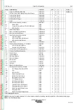
Page 27: ...Twist Mates Assembly M22415 10 2 X X 11a Switch Cover S27281 1 X X 11b Switch Bracket M21705 1 X X 11c M4 Plain Washer S26638 2 4 X X 11d M4 Lock Washer S26639 2 4 X X 11e M4 Hex Nut S26640 2 4 X X 11f Line Switch S27016 1 X X 11g Din Rail S27200 1 X X 11h M5x12 Combined Screw S28798 4 2 X X Display Board Assembly Includes L16640 1 1 X X 16 TFT Display Drive Board PCB S31891 1 X X 16a Nut NSS 2 X ...

Page 28: ... 21 Display Board Harness J14 Not Shown G8305 4 1 X X 22 Water Inlet Decal Not Shown S26743 22 1 X X 23 Water Gas Outlet Decal Not Shown S26743 17 1 X X 24 Gas Hose Not Shown E4306 2 1 X X 25 Hose Clamp Not Shown S26911 2 X X NOTE Use only the parts marked X in the column under the heading number called for in the model index page Index of Sub Assemblies Index of Sub Assemblies Index of Sub Assemb...

Page 29: ...17 10 1 2a 2b 2c 1a 1b 3 4 6 8 9 5 10 11 12 13 14 15 16 17 2d 3a 4a 5a 6a 7a 7 8a 9a 10a 11a 13a 13b 13c 13d 12b 15a 16b Index of Sub Assemblies Index of Sub Assemblies Index of Sub Assemblies Index of Sub Assemblies Part Numbers Part Numbers Part Numbers Part Numbers ...

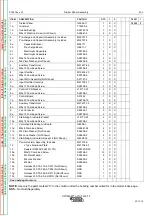
Page 30: ...X X 8a M5x12 Combined Screw S28798 4 4 X X 9 2x4 Connector S29444 1 2 X X 9a M4x16 Combined Screw S28798 13 2 X X 10 Stabilizing Arc Board Bracket L13173 29 2 X X 10a M5x12 Combined Screw S28798 4 2 X X 11 Varnished Stabilizing Arc Board G8296 1 1 X X 11a M4x8 Combined Screw S26641 38 4 X X 11b M4 Plain Washer Not Shown S26638 2 4 X X 11c M4 Lock Washer Not Shown S26639 2 4 X X 11d Stabilizing Arc...

Page 31: ... X X 18 Control Board J10 Harness Not Shown G8305 3 1 X X 19 Voltage Feedback Harness J4 Not Shown G8305 5 1 X X 20 Control Board J1 Harness Not Shown G8305 6 1 X X 21 Control Board J2 Drive Board J1 Harness Not Shown G8305 7 1 X X 22 Control Board J12 Harness Not Shown G8305 8 1 X X 23 Control Board J13 Harness Not Shown G8305 9 1 X X 24 Control Board J3 Drive Board J2 Harness Not Shown G8305 10 ...

Page 32: ...20 21 21 22 23 24 24a 24b 24b 24a 25 26 27 28 5e 4a 4b 4c 4d 6 5i 5j 5h 5f 5g 5h 6a 6b 6c 6d 6d 8e 8f 8g 8h 8j 8i 9a 10a 10b 11a 12a 13a 14 14a 16a 20a 18a 18b 19a 20b 21a 22a 23a 27a 27b 27c 27d Index of Sub Assemblies Index of Sub Assemblies Index of Sub Assemblies Index of Sub Assemblies Part Numbers Part Numbers Part Numbers Part Numbers ...

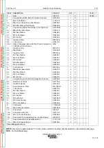
Page 33: ...41 8 2 X 6b M8 Plain Washer S26638 4 4 X 6c M8 Lock Washer S26639 4 2 X 6d M8 Hex Nut S26640 4 2 X 7 Copper Strap Arc Start Coil to Negative Terminal S27092 8 1 X 8a Resistor and Leads S27175 5 1 X 8b Insulation Spacer S26787 4 3 X 8c Small Aluminum Plate M21756 22 1 X 8d Tube Clamp S28416 4 1 X 8e M3 Plain Washer S26638 1 2 X 8f M3 Lock Washer S26639 1 2 X 8g M3 Hex Nut S26640 1 2 X 8h M10x235 Bo...

Page 34: ...ned Screw S28798 4 3 X 20b M5x20 Combined Screw S28798 12 2 X 21 Heatsink Support M24920 2 X 21a M5x20 Combined Screw S28798 12 2 X 22 Output Diode M22732 3 4 X 22a M6x16 Combined Screw S28798 7 8 X 22b Thermal Joint Compound Not Shown NSS X 23 IGBT Module M22734 5 1 X 23a M6x16 Combined Screw S28798 7 4 X 23b Thermal Joint Compound Not Shown NSS X 24 Bended Copper Strap S27092 29 4 X 24a M6x12 Co...

Page 35: ...8d M8 Hex Nut Not Shown S26640 4 1 X 29 Output Rectifier Thermostat Not Shown T13359 26 1 X 29a M3x10 Combined Screw Not Shown S28798 6 2 X 30 Output MOV Assembly Not Shown S27147 3 1 X NOTE Use only the parts marked X in the column under the heading number called for in the model index page Index of Sub Assemblies Index of Sub Assemblies Index of Sub Assemblies Index of Sub Assemblies Sub Assembl...

Page 36: ... PE 1 OPTIMARC AC DC 350 TP 2017 10 1 2 3 3a 4 4a 4b 4c 4d 5 5a 5b 5c 6 6a 7 7a 8 9 9a Index of Sub Assemblies Index of Sub Assemblies Index of Sub Assemblies Index of Sub Assemblies Part Numbers Part Numbers Part Numbers Part Numbers ...

Page 37: ...er S26638 2 2 X X 5b M4 Lock Washer S26639 2 2 X X 5c M4x30 Hex Head Screw S26641 3 2 X X 6 Input Holder Cover M20720 4 1 X X 6a M4x30 Hex Head Screw S26641 3 2 X X 7 Input Holder Base M20720 5 1 X X 7a M3x10 Combined Screw S28798 6 2 X X 8 Dust Cover S30264 3 1 X X 9 RS485 Connector Harness J8 Includes G8305 2 1 X X 9 2 9 Pins Connector S28574 2 NSS 1 X X 9a AST3 9x8 Self Tapping Screw S26738 7 2...

Page 38: ... Wraparound Assembly PF 1 OPTIMARC AC DC 350 TP 2017 10 1 2 3 4 5 6 Index of Sub Assemblies Index of Sub Assemblies Index of Sub Assemblies Index of Sub Assemblies Part Numbers Part Numbers Part Numbers Part Numbers ...

Page 39: ... S26738 2 3 X X 3 Right Case Side G5880 8 1 X X 3a M5x12 Hex Washer Head Philips Screw Not Shown S26641 4 5 X X 3b ST4 8x13 Hex Self Tapping Screw Not Shown S26738 2 3 X X 4 LE Logo NSS 2 X X 5 Label Case Top M20952 1 X 5 Label Case Top M20952 1 1 X 6 Wiring Diagram NSS 1 X X NOTE Use only the parts marked X in the column under the heading number called for in the model index page NSS Not Sold Sep...

Reviews: