A-8
INSTALLATION
MOBIFLEX 400-MS(/HE) BASE UNIT & LFA 3.1/4.1 MOBILE MANUAL/AUTOMATIC
A-8
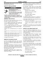
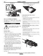
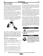
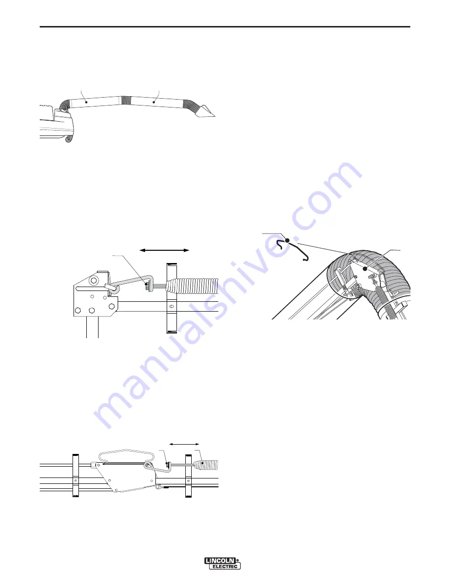
1. Bring the arm (including extraction hood) to a hori-
zontal position The arm should stay in this position.
See Figure A.13.
If the entire arm falls on its own:
(See Figure A.13 items A+B)
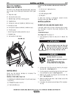
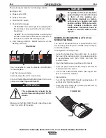
• Tighten bolt (A) in the hinge fan side to increase
spring tension. Ensure spring does not turn as you
tighten. See Figure A.14.
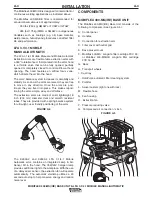
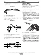
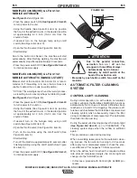
If the hood section of the arm falls on its own:
(See Figure A.13 item B)
• Tighten bolt (A) in middle hinge to increase spring (B)
tension. Ensure spring does not turn as you tighten.
See Figure A.15.
LFA 3.1/4.1 MOBILE
MANUAL/AUTOMATIC
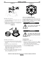
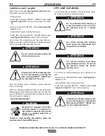
A hose running guard is attached to the middle hinge
of the extraction arm by a piece of tape.
See Figure A.16 for steps 1-9
1. Take the hose running guard (A) and snap it into
place at the middle hinge (B).
2. Fold back 2/3 of both rubber seals.
3. Remove the wrap from the flexible hose.
4. Place the flexible hose over both arm sections. To
secure the hose, at least one metal ring of the hose
should be applied over the ridges at each arm sec-
tion.
5. Fold back the rubber seals and place them over the
hose. The rubber seal should cover the arm section
0.5-1 inch.
Now mount the flexible hose at the hood side.
6. Fold back 2/3 of both rubber seals.
7. Remove the wrap from the flexible hose hood side.
8. Place the flexible hose over the hood and the arm
section hood side. To secure the hose, at least one
metal ring of the hose should be applied over the
ridges.
9. Fold back the rubber seals and place them over the
hose. The rubber seals should cover the hood and
the arm section 0.5-1 inch.
FIGURE A.13
A
B
FIGURE A.15
A
B
FIGURE A.14
A
FIGURE A.16
A
B


