49
Installation and Operations Guide
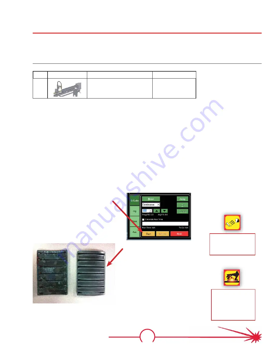
Step 30: Cut the speed test
With the pipe loaded on the machine, the speed test cut file loaded on the computer, the cor-
rect consumables for the selected amperage, and the plasma cutter’s compressed gas supply
available and its configuration set according to the cut charts, you are ready to cut the speed
test.
Qty
Part
Description
Part #
1
MPMP system
From Step 29
Required parts /
components
Instructions
• Check on the following pre-cut conditions:
• Cut file is loaded and TM4 shows “Connected” status.
• Air / gas supply is connected and in the correct pressure range.
• Air is being directed through the chuck.
• Correct amperage range has been selected for the installed
consumables.
• The torch height is correctly set.
• Click on the
Start
button to begin cutting.
Illustration
Click the
Start
button
WARNING
Cut parts retain heat
for many minutes.
Handle only with
approved tools until
fully cooled.
Lower speeds
Higher speeds
Select the cut with the least combi-
nation of bevel and dross. From the
file’s speed range, note the speed.
Wear eye protection
while watching the
plasma arc. Review
the safety chapter.
Summary of Contents for MASTERPIPE Mini Profiler
Page 9: ...1 Safety Guide Safety Information ...
Page 19: ...11 Installation and Operations Guide Hardware Installation ...
Page 62: ...54 MASTERPIPE Mini Profiler ...
Page 63: ...55 Driver Software Driver Introduction ...
Page 65: ...57 Driver Software Illustrations screen shots of the TM4 installation pro cess ...
Page 67: ...59 Driver Software Illustrations screen shots of the device driver installa tion process ...
Page 96: ...88 MASTERPIPE Mini Profiler ...
Page 97: ...89 Installation and Operations Guide Parts ...
Page 100: ...92 MASTERPIPE Mini Profiler ...
Page 101: ...93 Installation and Operations Guide Troubleshooting ...


