A-9
INSTALLATION
MODULAR FUME HOOD
™
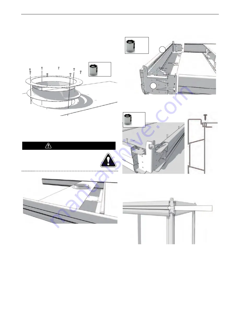
14. Determine position and number of connection flanges
according to S31225-77 Table. Refer the assembly
references section of the manual.
15. Make necessary cutout(s) in “A-TOP” roof panel(s), using the
inner flange ring as a template.
16. Mount connection flange(s). See Figure A.10.
FIGURE – A.10
17. Continue to place the “B-BOTTOM” roof panels with side
distance holders, “A-TOP” roof panels, H-profiles and vertical
spacers (if applicable) and “C-BOTTOM END” roof panel at
the end with distance holders except for the last “A-TOP”
roof panel. See Figure A.11.
Corner cut-out to be added for the last “A-TOP”
roof panel as per figure A.5 and in case of leg
mounting, make sure to use the “C-BOTTOM
END” panel with corner cut-out as per Figure A.6
FIGURE – A.11
18. Mount the remaining inner and outer corner pieces (1) and
main frame profile (2). See Figure A.12.
FIGURE – A.12
19. Place the last “A-TOP” roof panel and fasten them all. See
Figure A.13.
FIGURE – A.13
20. Slide the branding strips in the main frame profiles. See
Figure A.14.
FIGURE A.14
7 mm
1
2
10 mm
7 mm
ATTENTION


