


English
English
44
36
38
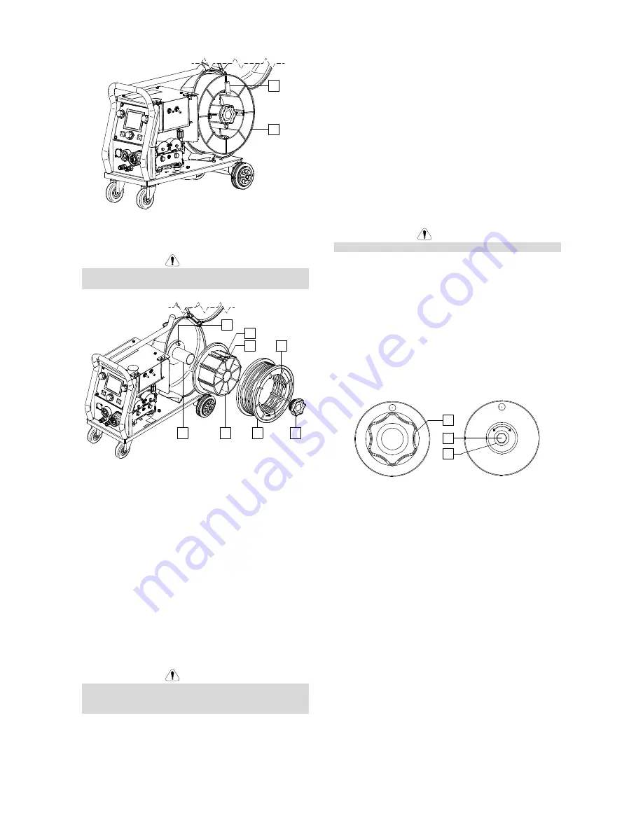
Figure 96
Wire Spool Type Readi-Reel
®
Loading
WARNING
Turn the input power OFF at the welding power source
before installation or changing a wire spool.
28
43
40
30
31
42
41
39
Figure 97
••••
Turn the input power OFF.
••••
Open the spool wire case.
••••
Unscrew the Locking Nut [28] and remove it from the
Spindle [30].
••••
Place the adapter of spool type Readi-Reel
®
[40] on
the spindle [30]. Make certain that the spindle brake
pin [31] is put in the hole in the back side of the
adapter [40]. The adapter of spool type Readi-Reel
®
can be purchased separately (see "Accessories"
chapter).
••••
Re-install the locking nut [28]. Make sure that the
locking nut is tightened.
••••
Rotate the spindle and adapter so the retaining
spring [41] is at the 12 o'clock position.
••••
Place the spool type Readi-Reel
®
[43] on the adapter
[40]. Set one of the Readi-Reel
®
inside cage wires
[39] on the slot [42] in the retaining spring tab [41].
WARNING
Position the spool type Readi-Reel
®
so that it will rotate
in a direction when feeding so as to be de-reeled from
bottom of the spool.
Loading the Electrode Wire
•
Turn the input power OFF.
•
Open the spool wire case.
•
Unscrew the locking nut of the sleeve.
•
Load the spooled wire on the sleeve such that the
spool turns clockwise when the wire is fed into the
wire feeder.
•
Make sure that the spindle brake pin [38] goes into
the fitting hole on the spool.
•
Screw in the locking nut of the sleeve.
•
Open the wire drive door.
•
Put on the wire roll using the correct groove
corresponding to the wire diameter.
•
Free the end of the wire and cut off the bent end
making sure it has no burr.
WARNING
Sharp end of the wire can hurt.
•
Rotate the wire spool clockwise and thread the end
of the wire into the wire feeder as far as the Euro
Socket.
•
Adjust force of pressure roll of the wire feeder
properly.
Adjustments of Brake Torque of Sleeve
To avoid spontaneous unrolling of the welding wire the
sleeve is fitted with a brake.
Adjustment is carried by rotation of its screw M10, which
is placed inside of the sleeve frame after unscrewing the
locking nut of the sleeve.
28
44
45
Figure 98
28. Locking Nut.
44. Adjusting Screw M10.
45. Pressing Spring.
Turning the screw M10 clockwise increases the spring
tension and you can increase the brake torque
Turning the screw M10 anticlockwise decreases the
spring tension and you can decrease the brake torque.
After finishing of adjustment, you should screw in the
locking nut again.


