
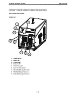


PIPEFAB™ WELDING SYSTEM
INSTALLATION
A-27
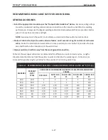
RECOMMENDED WORK CABLE SIZES FOR ARC WELDING
GENERAL GUIDELINES
•
Select the appropriate size cables per the “Output Cable Guidelines” below.
Excessive voltage drops
caused by undersized welding cables and poor connec
�
ons o
�
en result in unsa
�
sfactory welding
performance. Always use the largest welding cables (electrode and work) that are prac
�
cal, and be
sure all connec
�
ons are clean and
�
ght.
NOTE:
Excessive heat in the weld circuit indicates undersized cables and/or bad connec
�
ons.
•
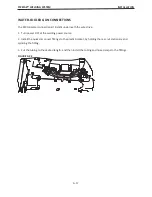
Route all cables directly to the work and wire feeder, avoid excessive lengths and do not coil excess
cable.
Route the electrode and work cables in close proximity to one another to minimize the loop
area and therefore the inductance of the weld circuit.
•
Always weld in a direc
�
on away from the work (ground) connec
�
on.
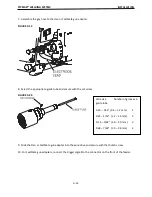
Table A.1 shows copper cable sizes recommended for di
ff
erent currents and duty cycles. Lengths
s
�
pulated are the distance from the welder to work and back to the welder again. Cable sizes are
increased for greater lengths primarily for the purpose of minimizing cable drop.
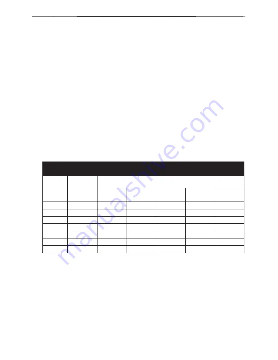
TABLE A.1 - RECOMMENDED CABLE SIZES - RUBBER COVERED COPPER - RATED 167°F (75°C)[1]
AMPERES
PERCENT
DUTY
CYCLE
CABLE SIZES FOR COMBINED LENGTHS OF ELECTRODE AND WORK
CABLES
0 TO 50 FT.
50 TO 100
FT.
100 TO 150
FT.
150 TO 200
FT.
200 TO 250
FT.
200
100
2
2
2
1
1/0
250
100
1
1
1
1
1/0
300
100
2/0
2/0
2/0
2/0
3/0
400
100
3/0
3/0
3/0
3/0
4/0
450
100
3/0
3/0
4/0
4/0
2–3/0
500
60
2/0
2/0
3/0
3/0
4/0
550
40
2/0
2/0
3/0
3/0
4/0
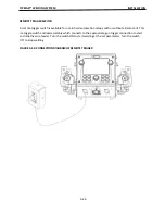
Summary of Contents for PIPEFAB CE
Page 18: ...PIPEFAB WELDING SYSTEM INSTALLATION A 3 FIGURE A 1 ...
Page 97: ......


