background image

SVM209-A

April, 2011

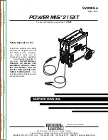
Safety Depends on You

Lincoln  arc  welding  and  cutting
equipment  is  designed  and  built
with  safety  in  mind.    However,
your  overall  safety  can  be
increased  by  proper  installation
.  .  .  and  thoughtful  operation  on
your  part.   

DO NOT  INSTALL,

OPERATE  OR  REPAIR  THIS
EQUIPMENT  WITHOUT  READ-
ING  THIS  MANUAL  AND  THE
SAFETY  PRECAUTIONS  CON-
TAINED  THROUGHOUT.

And,

most importantly, think before you
act and be careful.

SERVICE MANUAL

For use with machine code number: 

11521

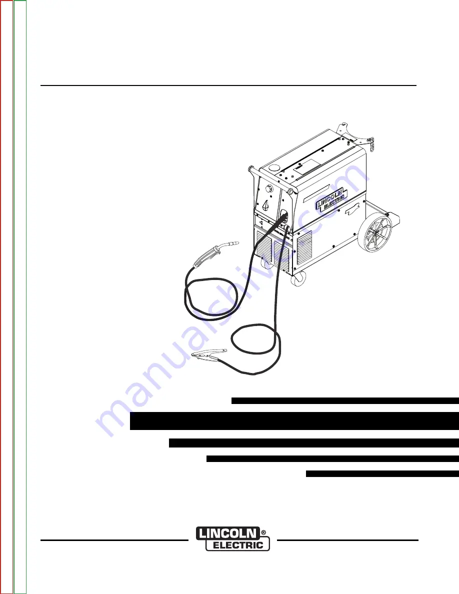
POWER MIG

® 

215XT

• Sales and Service through Subsidiaries and Distributors Worldwide •

Cleveland, Ohio 44117-1199  U.S.A.   TEL: 216.481.8100   FAX: 216.486.1751   WEB SITE: www.lincolnelectric.com

• World's Leader in Welding and Cutting Products •

Copyright © Lincoln Global Inc.

Return 

to 

Master 

T

OC

Return 

to 

Master 

T

OC

Return 

to 

Master 

T

OC

Return 

to 

Master 

T

OC

V

iew 

Safety 

Info

V

iew 

Safety 

Info

V

iew 

Safety 

Info

V

iew 

Safety 

Info

Summary of Contents for POWER MIG 11521

Page 1: ...N TAINED THROUGHOUT And most importantly think before you act and be careful SERVICE MANUAL For use with machine code number 11521 POWER MIG 215XT Sales and Service through Subsidiaries and Distributors Worldwide Cleveland Ohio 44117 1199 U S A TEL 216 481 8100 FAX 216 486 1751 WEB SITE www lincolnelectric com World s Leader in Welding and Cutting Products Copyright Lincoln Global Inc Return to Ma...

Page 2: ...THEIR DOCTOR BEFORE OPERATING Read and understand the following safety highlights For additional safety information it is strongly recommended that you purchase a copy of Safety in Welding Cutting ANSI Standard Z49 1 from the American Welding Society P O Box 351040 Miami Florida 33135 or CSA Standard W117 2 1974 A Free copy of Arc Welding Safety booklet E205 is available from the Lincoln Electric ...

Page 3: ...pen arc welding Headshield and filter lens should conform to ANSI Z87 I standards 4 b Use suitable clothing made from durable flame resistant material to protect your skin and that of your helpers from the arc rays 4 c Protect other nearby personnel with suitable non flammable screening and or warn them not to watch the arc nor expose themselves to the arc rays or to hot spatter or metal ELECTRIC ...

Page 4: ... near hydraulic lines Have a fire extinguisher readily available 6 b Where compressed gases are to be used at the job site special precautions should be used to prevent hazardous situations Refer to Safety in Welding and Cutting ANSI Standard Z49 1 and the operating information for the equipment being used 6 c When not welding make certain no part of the electrode circuit is touching the work or g...

Page 5: ...outtes de laitier en fusion sont émises de l arc de soudage Se protéger avec des vêtements de protection libres de l huile tels que les gants en cuir chemise épaisse pan talons sans revers et chaussures montantes 5 Toujours porter des lunettes de sécurité dans la zone de soudage Utiliser des lunettes avec écrans lateraux dans les zones où l on pique le laitier 6 Eloigner les matériaux inflammables...

Page 6: ...ance of the manufacturer In some cases this remedial action may be as simple as earthing grounding the welding circuit see Note In other cases it could involve construction of an electromagnetic screen enclosing the power source and the work com plete with associated input filters In all cases electromagnetic disturbances must be reduced to the point where they are no longer troublesome Note The w...

Page 7: ...uld be kept as short as possible and should be positioned close together running at or close to floor level Equipotential Bonding Bonding of all metallic components in the welding installation and adjacent to it should be considered However metallic components bonded to the work piece will increase the risk that the operator could receive a shock by touching these metallic components and the elect...

Page 8: ...NS I I Power MIG 215XT Page Safety i vi Installation Section A Operation Section B Accessories Section C Maintenance Section D Theory of Operation Section E Troubleshooting and Repair Section F Electrical Diagrams Section G Parts Manual P 580 ...

Page 9: ...ety Precautions A 3 Uncrating the POWER MIG 215XT A 3 Location A 3 Input Power Grounding and Connection Diagrams A 3 Output Polarity Connections A 4 Gun and Cable Installation A 5 Shielding Gas A 5 Auxiliary Power Receptacles A 5 Return to Master TOC Return to Master TOC Return to Master TOC Return to Master TOC ...

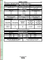
Page 10: ...DIMENSIONS Wire Speed 50 700 IPM 1 27 17 8 m minute WIRE SPEED RANGE Standard Voltage Phase Frequency Input Current 170 Amp Rated Output Input Current 215 Amp Rated Output 208 230 1 50 60 Hz With 115V receptacle loaded to 15A With 115V receptacle loaded to 15A 39 35 Amps 45 41 Amps TEMPERATURE RANGES STORAGE TEMPERATURE RANGE 40 F to 185 F 40 C to 40 C OPERATING TEMPERATURE RANGE 4 F to 104 F 20 C...

Page 11: ...ve foam and corrugated packing material Untape accessories from Gas Bottle Platform Unscrew the two wood screws at the Gas Bottle Platform holding the machine to the skid Roll the machine off the skid assembly LOCATION Locate the welder in a dry location where there is free circulation of clean air into the louvers in the back and out the front A location that minimizes the amount of smoke and dir...

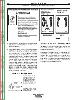
Page 12: ...elder plug is insert ed into a grounded receptacle FIGURE A 2 Receptacle Diagram CONNECT TO A SYSTEM GROUNDING WIRE SEE THE UNITED STATES NATIONAL ELECTRICAL CODE AND OR LOCAL CODES FOR OTHER DETAILS AND MEANS FOR PROPER GROUNDING CONNECT TO HOT WIRES OF A THREE WIRE SINGLE PHASE SYSTEM 50 60 HZ FIGURE A 1 Dual Voltage Machine Input Connections OUTPUT POLARITY CONNECTIONS The welder as shipped fro...

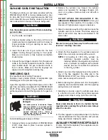
Page 13: ... Oil or grease in the presence of high pressure oxygen is explosive 3 Stand to one side away from the outlet and open the cylinder valve for an instant This blows away any dust or dirt which may have accumulated in the valve outlet Be sure to keep your face away from the valve out let when cracking the valve 4 Attach the flow regulator to the cylinder valve and tighten the union nut s securely wit...

Page 14: ...NOTES A 6 A 6 Power MIG 215XT Return to Section TOC Return to Section TOC Return to Section TOC Return to Section TOC Return to Master TOC Return to Master TOC Return to Master TOC Return to Master TOC ...

Page 15: ...for Changing Drive Roll B 4 Wire Reel Loading B 4 Mounting of 10 to 30 lbs Spools B 4 To Start the Welder B 5 Feeding Electrode B 5 Idle Roll Pressure Setting B 5 Wire Drive Configuration B 5 B 6 Making a Weld B 6 Avoiding Wire Feeding Problems B 7 Fan Control B 7 Input Line Voltage Protection B 7 Wire Feed Overload Protection B 7 Welding Thermal Overload Protection B 7 Welding Procedure Informati...

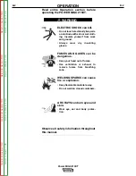
Page 16: ...gerous Keep your head out of fumes Use ventilation or exhaust to remove fumes from breathing zone WELDING SPARKS can cause fire or explosion Keep flammable material away Do not weld on closed containers ARC RAYS can burn eyes and skin Wear eye ear and body protec tion Observe all safety information throughout this manual WARNING Return to Section TOC Return to Section TOC Return to Section TOC Ret...

Page 17: ...uty cycle or 250A 40 duty cycle rated 15 ft 3 6 m GMAW gun and cable assembly equipped for these wire sizes Use of GMAW processes requires a supply of shielding gas WELDING CAPABILITY The POWER MIG 215XT is rated at 215 amps 22 volts at a 30 duty cycle based on a ten minute cycle time It is capable of higher duty cycles at lower output currents The tapped transformer design makes it well suited fo...

Page 18: ...ke sure that the Release Bar pops up and that the collar retainers fully engage the retaining ring groove on the spindle 5 Rotate the spindle and adapter so the retaining spring is at the 12 o clock position 6 Position the Readi Reel so that it will rotate in a direction when feeding so as to be de reeled from top of the coil 7 Set one of the Readi Reel inside cage wires on the slot in the retaini...

Page 19: ...er source before installation or changing drive rolls and or guides Do not touch electrically live parts When inching with the gun trigger electrode and drive mechanism are hot to work and ground and could remain energized several seconds after the gun trigger is released Only qualified personnel should perform mainte nance work The pressure arm controls the amount of force the drive rolls exert o...

Page 20: ... connector bar against the gun bushing Important Do not attempt to completely remove the socket head cap screw 6 Remove the outer wire guide and push the gun bushing out of the wire drive Because of the pre cision fit light tapping may be required to remove the gun bushing 7 Disconnect the shielding gas hose from the gun bushing if required 8 Connect the shielding gas hose to the new gun bushing i...

Page 21: ...hen using Innershield electrode the gas nozzle may be removed from the insulation on the end of the gun and replaced with the gas less nozzle This will give improved visibility and eliminate the possibility of the gas nozzle overheating AVOIDING WIRE FEEDING PROBLEMS Wire feeding problems can be avoided by observing the following gun handling procedures 1 Do not kink or pull cable around sharp cor...

Page 22: ...NOTES B 8 B 8 Power MIG 215XT Return to Section TOC Return to Section TOC Return to Section TOC Return to Section TOC Return to Master TOC Return to Master TOC Return to Master TOC Return to Master TOC ...

Page 23: ...e Assemblies C 2 Magnum Gun Connection Kit C 2 Optional Spool Guns and Adapters C 2 Magnum 250XL Push Pull Gun and Adapter C 3 Connecting The Magnum 250lx Push Pull Gun and Magnum 250LX Push Pull Gun Adapter C 3 Make a Weld with the Magnum 250LX Push Pull Gun C 3 Making a Weld with the Spool Gun Adapter Kit and Spool Gun Installed C 4 Return to Master TOC Return to Master TOC Return to Master TOC ...

Page 24: ... the wire sizes specified Unplug or Disconnect all input power from the POWER MIG 215XT before installing the Spool Gun and Kit MAGNUM GUN CONNECTION KIT Optional K466 6 Using the optional K466 6 Magnum Connection kit for the POWER MIG 215XT permits use of standard Magnum 200 300 or 400 gun and cable assemblies OPTIONAL SPOOL GUNS AND ADAPTERS The Power MIG 215XT is capable of operating with the f...

Page 25: ...ER K2705 1 See Figure C 1 1 Plug the 115 VAC cable into available 115V AC recep tacle The Power MIG 215XT K2701 1 furnishes the 15A 115V AC auxiliary supply The receptacle is located at the back of the machine 2 Connect the 4 pin connector cable of the Push Pull Gun Adapter to the 4 pin trigger receptacle located in the front section of the wire drive compartment 3 Connect the 7 pin connector cabl...

Page 26: ...pool gun operation and spool gun gas solenoid valve Closing spool gun trigger starts spool gun weld ing and makes both electrodes electrically HOT 3 Operation with POWER MIG 215XT Turn the POWER MIG 215XT input power ON Adjusting the voltage tap control will increase or decrease your welding voltage Adjusting the wire speed control on the spool gun will increase or decrease the spool gun wire feed...

Page 27: ...intenance D 2 Drive Rolls and guide Tubes D 2 Contact Tip and Gas Nozzle Installation D 2 Gun Tubes and Nozzles D 2 Gun Cable Cleaning D 2 Liner Removal and Replacement D 3 Gun Handle Disassembly D 4 Major Component Locations D 5 Return to Master TOC Return to Master TOC Return to Master TOC Return to Master TOC ...

Page 28: ...HOCK can kill Have an electrician install and service this equipment Turn the input power off at the fuse box before working on equipment Do not touch electrically hot parts GENERAL MAINTENANCE In extremely dusty locations dirt may clog the air pas sages causing the welder to run hot Blow dirt out of the welder with low pressure air at regular intervals to eliminate excessive dirt and dust build u...

Page 29: ...the gas diffuser from the gun tube 3 Lay the gun and cable out straight on a flat surface Loosen the set screw located in the brass connec tor at the feeder end of the cable and pull the liner out of the cable 4 Insert a new untrimmed liner into the connector end of the cable Be sure the liner bushing is stencilled appropriately for the wire size bing used 5 Fully seat the liner bushing into the c...

Page 30: ... 030 0 8 mm KP2020 1B1 035 0 9 mm KP2020 2B1 045 1 2 mm Heavy Duty KP2021 1B1 035 0 9 mm KP2020 2B1 045 1 2 mm Tapered KP2022 5B1 025 0 6 mm KP2022 6B1 030 0 8 mm KP2022 1B1 035 0 9 mm KP2022 2B1 045 1 2 mm Tab For Aluminum KP2010 5B1 3 64 1 2 mm Alum Wire Alum Wire GAS NOZZLES Fixed Flush KP1931 1 3 8 9 5 mm KP1931 2 1 2 12 7 mm KP1931 3 5 8 15 9 mm Fixed Recessed KP1930 1 3 8 9 5 mm KP1930 2 1 2...

Page 31: ...Wire Drive Assembly 5 Base Power Component Assembly 6 Covers Assembly 6 6 2 2 3 3 4 4 5 5 1 1 FIGURE D 2 MAJOR COMPONENT LOCATIONS Return to Section TOC Return to Section TOC Return to Section TOC Return to Section TOC Return to Master TOC Return to Master TOC Return to Master TOC Return to Master TOC ...

Page 32: ...NOTES D 6 D 6 Power MIG 215XT Return to Section TOC Return to Section TOC Return to Section TOC Return to Section TOC Return to Master TOC Return to Master TOC Return to Master TOC Return to Master TOC ...

Page 33: ...its E 5 Thermal Overload Protection E 5 Wirefeed Overload Protection E 5 FIGURE E 1 BLOCK LOGIC DIAGRAM LINE SWITCH RECONNECT PANEL FAN MOTOR CONTROL BOARD GAS SOLENOID WIRE SPEED CONTROL SPOOL GUN SWITCH WIRE DRIVE MOTOR TACH FEEDBACK GUN TRIGGER OUTPUT DIODE BRIDGE NEGATIVE TERMINAL CONTACTOR CONTACTOR CONTROL TAP SELECTOR SWITCH OUTPUT CHOKE POSITIVE TERMINAL TRANSFORMER THERMOSTAT OUTPUT BRIDG...

Page 34: ... is coupled to a voltage selector switch By selecting one of seven positions on the switch the user can preset the desired voltage output from a minimum setting A to a maximum voltage setting G FIGURE E 2 INPUT POWER CIRCUIT LINE SWITCH RECONNECT PANEL FAN MOTOR CONTROL BOARD GAS SOLENOID WIRE SPEED CONTROL SPOOL GUN SWITCH WIRE DRIVE MOTOR TACH FEEDBACK GUN TRIGGER OUTPUT DIODE BRIDGE NEGATIVE TE...

Page 35: ...pplied to the output terminals of the machine FIGURE E 2 CONTROL CIRCUITS LINE SWITCH RECONNECT PANEL FAN MOTOR CONTROL BOARD GAS SOLENOID WIRE SPEED CONTROL SPOOL GUN SWITCH WIRE DRIVE MOTOR TACH FEEDBACK GUN TRIGGER OUTPUT DIODE BRIDGE NEGATIVE TERMINAL CONTACTOR CONTACTOR CONTROL TAP SELECTOR SWITCH OUTPUT CHOKE POSITIVE TERMINAL TRANSFORMER THERMOSTAT OUTPUT BRIDGE THERMOSTAT MAIN TRANSFORMER ...

Page 36: ...ive heat the trigger circuit would be interrupted and the machine s output and the wire feed would be disabled The board also contains overload protection circuitry which protects the drive motor from excessive current draw The Power MIG 215XT is equipped with an adapter panel and switch to allow operation of a spool gun for feeding aluminum wires LINE SWITCH RECONNECT PANEL FAN MOTOR CONTROL BOAR...

Page 37: ...e left on and the reset should occur within a 15 minute period If the fan is not turning or the air intake louver are obstructed then the input power must be removed and the fan problem or air obstruction must be corrected WIREFEED OVERLOAD PROTECTION The Power MIG 215XT has solid state overload protection of the wire drive motor If the motor becomes overloaded the protection circuitry turns off t...

Page 38: ...NOTES E 6 E 6 Power MIG 215XT Return to Section TOC Return to Section TOC Return to Section TOC Return to Section TOC Return to Master TOC Return to Master TOC Return to Master TOC Return to Master TOC ...

Page 39: ...lacement F 27 Wire Drive Motor Assembly Replacement F 29 Output Diode Bridge Rectifier Replacement F 33 Output Capacitors Replacement F 37 Main Transformer Replacement F 41 Fan Blade Motor Replacement F 47 Output Contactor Replacement F 49 Retest After Repair F 52 ELECTRIC SHOCK can kill Never work on the inside of the machine without removing the input power You can receive a life threatening ele...

Page 40: ...mponents in the order listed to eliminate one possibility at a time until you locate the cause of your problem All of the referenced test procedures referred to in the Troubleshooting Guide are described in detail at the end of this chapter Refer to the Troubleshooting and Repair Table of Contents to locate each specific Test Procedure All of the specified test points components terminal strips et...

Page 41: ... paper plastic or cloth which could have a static charge If the PC board can t be installed immediately put it back in the static shield ing bag If the PC board uses protective shorting jumpers don t remove them until installation is complete If you return a PC board to The Lincoln Electric Company for credit it must be in the static shielding bag This will prevent further damage and allow prop er...

Page 42: ...eck the input power switch S1 It may be faulty 2 Check for broken or missing wires at the reconnect panel 3 Perform the Main Transformer Test There is no open circuit voltage or wire feed when the gun trigger is activated The cooling fan is running 1 Make sure the input voltage is correct and matches the nameplate rating and reconnect panel configuration 2 One of the two thermostats may be open du...

Page 43: ... it is set to the normal position if using the Power MIG 215XT built in wire feeder When the gun trigger is activated and the wire feeds normally but there is no open circuit voltage 1 Make sure the gun cable and work cables are connected prop erly and in good condition 2 Make sure the output selector switch is in a good condition posi tion and not between positions 1 Check the output selector swi...

Page 44: ...ltage being applied 2 Make sure the settings for wire feed speed and voltage are cor rect for the process being used 3 Make sure the electrode polarity is correct for the process being used 4 Check the welding cables and gun for loose or faulty connec tions 1 Check for loose or faulty con nections on the heavy current carrying leads inside the Power MIG 215XT See the Wiring Diagram 2 The output ca...

Page 45: ...e gas solenoid by discon necting it from leads 108A and 116A B Apply a 12VDC external supply to the solenoid If the sole noid does NOT activate then it may be faulty Replace The machine stops feeding wire while welding When the gun trig ger is released and pulled again the wire feed starts 1 Check for a mechanical restriction in the wire feed path The gun may be clogged 2 Make sure the drive rolls...

Page 46: ...eral times and check if the problem is resolved 1 The wire speed control potentiome ter may be faulty Check or replace Normal potentiometer resistance is 10K ohms 2 Perform the Wire Drive Motor and Tachometer Feedback Test 3 The control board may be faulty There is no wire feed when the gun trigger is activated Normal open circuit weld voltage is present and the gas solenoid functions normal ly 1 ...

Page 47: ...y 2 Perform the Output Bridge Rectifier Test The arc is unstable and or hunting 1 Check for a worn or melted con tact tip 2 Check for loose or faulty connec tions on the work and gun cables 3 Make sure the electrode polarity is correct for the welding process being used 4 Check for rusted or dirty electrode wire 5 Make sure the machine s settings and shielding gas are correct for the process being...

Page 48: ...lding gas is correct and the flow is proper 3 Make sure the weld joint is not contaminated 1 Perform the Output Bridge Rectifier Test 2 The output capacitors may be faulty Check for loose connections at the capacitors Also check for leaky capacitors Replace if necessary WARNING The liquid electrolyte in these capacitors is toxic Avoid contact with any portion of your body The contact tip seizes in...

Page 49: ...s safely contact the Lincoln Electric Service Department for electrical trou bleshooting assistance before you proceed Call 1 888 935 3877 TEST DESCRIPTION This test will determine if the correct voltages are being applied a Applied to the primary windings of the Main Transformers b Induced on the secondary and auxiliary windings of the Main Transformer MATERIALS NEEDED 3 8 wrench 5 16 Nutdriver V...

Page 50: ...n the output rectifier assembly See Figure F 2 6 Locate leads X9 and X10 See Figure F 3 7 Connect main input power to the machine 8 Turn the Power MIG 215XT ON OFF Power Switch to the ON position 9 Carefully make the following voltage tests See Table F 1 10 Turn Off the machine 11 If any of the voltages are incorrect or missing check for loose or broken connections between the main transformer and...

Page 51: ...AIN TRANSFORMER TEST continued TROUBLESHOOTING AND REPAIR F 13 F 13 Power MIG 215XT Return to Section TOC Return to Section TOC Return to Section TOC Return to Section TOC Return to Master TOC Return to Master TOC Return to Master TOC Return to Master TOC ...

Page 52: ...ct nameplate voltage is being applied to the main transformer and one or more of the secondary voltages are missing or are incorrect the main transformer may be faulty Replace 14 When test is complete replace tool tray case sides and top TROUBLESHOOTING AND REPAIR F 14 F 14 Power MIG 215XT INPUT VOLTAGE TEST POINTS EXPECTED VOLTAGE READING 11 9 13 0 VAC 14 1 15 2 VAC 16 2 17 5 VAC 18 4 19 7 VAC 20...

Page 53: ...s or are unable to perform the test repairs safely contact the Lincoln Electric Service Department for electrical trou bleshooting assistance before you proceed Call 1 888 935 3877 TEST DESCRIPTION This test will determine if the Wire Drive Motor and Voltage Feedback Circuit are functioning properly MATERIALS NEEDED 5 16 Nutdriver Volt Ohmmeter WIRE DRIVE MOTOR AND TACHOMETER FEEDBACK TEST TROUBLE...

Page 54: ...main input power to the machine 2 Open the side panels and remove the tool tray using a 5 16 nutdriver 3 Locate plug J4 on the wiring harness See Wiring Diagram 4 Locate the black and white armature leads on plug J4 See Figure F 4 TROUBLESHOOTING AND REPAIR F 16 F 16 Power MIG 215XT Return to Section TOC Return to Section TOC Return to Section TOC Return to Section TOC Return to Master TOC Return ...

Page 55: ... into the lead side of plug J4 6 If the 5 6 VDC is present check the leads to the tachometer circuit 7 If the leads are okay and 5 6 VDC is present the correct voltage is being received from the con trol PC board Continue with the supply voltage to tachometer test 8 If the 5 6 VDC is not present and the leads are okay the control PC board may be faulty replace the control PC board Also check plug ...

Page 56: ...ent or NOT correct the control PC board is not receiving the proper feedback voltage from the tachometer circuit 7 If the leads are okay the tachometer circuit may be faulty replace the tachometer circuit 8 Replace the tool tray WIRE DRIVE MOTOR AND TACHOMETER FEEDBACK TEST continued TROUBLESHOOTING AND REPAIR F 18 F 18 Power MIG 215XT FIGURE F 5 PLUG J4 Black Tach J11 J11 Black Arm White Arm Blue...

Page 57: ...test repairs safely contact the Lincoln Electric Service Department for electrical trou bleshooting assistance before you proceed Call 1 888 935 3877 TEST DESCRIPTION This test will determine if a diode is shorted or leaky See the machine waveform section in this manual for normal and abnormal output wave forms MATERIALS NEEDED Analog Volt ohmmeter or Diode Tester 3 8 Nutdriver 1 2 Nutdriver OUTPU...

Page 58: ...Test for shorted or leaky diodes by checking from the anodes to the cathodes of the diode heatsink plates The readings should be high resistance in one polarity and low resistance in the opposite polarity 5 If any of the diodes are leaky or shorted the output rectifier assembly should be replaced 6 When the test is complete replace the negative output lead previously removed 7 Replace the left cas...

Page 59: ... not understand the test procedures or are unable to perform the test repairs safely contact the Lincoln Electric Service Department for electrical trou bleshooting assistance before you proceed Call 1 888 935 3877 TEST DESCRIPTION This test will determine if the Contactor is functional MATERIALS NEEDED 12 VDC Supply Volt Ohmmeter 7 16 Wrench CONTACTOR TEST TROUBLESHOOTING AND REPAIR F 21 F 21 Pow...

Page 60: ...place 7 If the contactor activates when the 12VDC is applied check the resistance between the two large terminals with the contactor activated The resistance should be very low 0 to 1 ohm 8 If the resistance is high or open between the two large terminals when the contactor is acti vated the contactor is faulty Replace 9 If the contactor activates and the resistance between the terminals is low wh...

Page 61: ...ed at machine output terminals probe to electrode probe to work SCOPE SETTINGS Volts Div 10V Div Horizontal Sweep 5 ms Div Coupling DC Trigger Internal TYPICAL OUTPUT VOLTAGE WAVEFORM MACHINE LOADED MAX TAP G 0 volts 5ms 10 0V TROUBLESHOOTING AND REPAIR F 23 F 23 Power MIG 215XT MACHINE LOADED TO 200 AMPS AT 22 VDC Return to Section TOC Return to Section TOC Return to Section TOC Return to Section...

Page 62: ...at machine output terminals probe to electrode probe to work SCOPE SETTINGS Volts Div 20V Div Horizontal Sweep 1 0 ms Div Coupling DC Trigger Internal NORMAL OPEN CIRCUIT VOLTAGE WAVEFORM MAX TAP G 0 volts 1 0 ms 20 0V TROUBLESHOOTING AND REPAIR F 24 F 24 Power MIG 215XT Return to Section TOC Return to Section TOC Return to Section TOC Return to Section TOC Return to Master TOC Return to Master TO...

Page 63: ... bank Note Scope probes connected at machine output terminals probe to electrode probe to work ABNORMAL OUTPUT VOLTAGE WAVEFORM MACHINE LOADED MAX TAP G ONE OUTPUT DIODE NOT FUNCTIONING 0 volts 5ms 20 0 V TROUBLESHOOTING AND REPAIR F 25 F 25 Power MIG 215XT SCOPE SETTINGS Volts Div 20V Div Horizontal Sweep 5 ms Div Coupling DC Trigger Internal MACHINE LOADED TO 180 AMPS AT 16 VDC Return to Section...

Page 64: ...te Scope probes connected at machine output terminals probe to electrode probe to work SCOPE SETTINGS Volts Div 20V Div Horizontal Sweep 5 ms Div Coupling DC Trigger Internal ABNORMAL OPEN CIRCUIT VOLTAGE OUTPUT CAPACITOR BANK NOT FUNCTIONING MAX TAP G 0 volts 5ms 20 0 V TROUBLESHOOTING AND REPAIR F 26 F 26 Power MIG 215XT Return to Section TOC Return to Section TOC Return to Section TOC Return to...

Page 65: ...t procedures or are unable to perform the test repairs safely contact the Lincoln Electric Service Department for electrical trou bleshooting assistance before you proceed Call 1 888 935 3877 TEST DESCRIPTION The following procedure will aid the technician in removing the Control Board for replacement MATERIALS NEEDED 5 16 Nutdriver CONTROL BOARD REMOVAL AND REPLACEMENT PROCEDURE TROUBLESHOOTING A...

Page 66: ...the control board 5 Depress the retaining pins on the sides of the four nylon mounts to release the control board See Figure F 8 6 Carefully remove the control board 7 Mount the new board to the nylon mounting pins 8 Reconnect any plugs or leads previously removed 9 Replace the tool tray previously removed TROUBLESHOOTING AND REPAIR F 28 F 28 Power MIG 215XT Return to Section TOC Return to Section...

Page 67: ... the test repairs safely contact the Lincoln Electric Service Department for electrical trou bleshooting assistance before you proceed Call 1 888 935 3877 TEST DESCRIPTION The following procedure will aid the technician in removing the Wire Drive and Tachometer for repair or replacement MATERIALS NEEDED 5 16 Nutdriver 9 16 Nutdriver Pliers Small Flathead Screwdriver WIRE DRIVE MOTOR REMOVAL AND RE...

Page 68: ...connect lead from the wire drive motor assembly not the machine 5 Using a 5 16 nutdriver remove the three mounting screws next to the wire drive assem bly See Figure F 10 6 Using a 5 16 nutdriver remove the two screws on the case front assembly See Figure F 11 7 Carefully maneuver the wire drive assembly out the side of the machine to gain access to plug J4 See Wiring Diagram 8 Disconnect plug J4 ...

Page 69: ...F 11 MOUNTING SCREW LOCATIONS WIRE DRIVE MOTOR REMOVAL AND REPLACEMENT PROCEDURE continued TROUBLESHOOTING AND REPAIR F 31 F 31 Power MIG 215XT Return to Section TOC Return to Section TOC Return to Section TOC Return to Section TOC Return to Master TOC Return to Master TOC Return to Master TOC Return to Master TOC ...

Page 70: ...nting screws previously removed 5 Using a 3 4 nut driver replace the thick black lead previously removed 6 Reconnect the gas hose to the wire drive assembly 7 Close case wrap around cover TROUBLESHOOTING AND REPAIR F 32 F 32 Power MIG 215XT Return to Section TOC Return to Section TOC Return to Section TOC Return to Section TOC Return to Master TOC Return to Master TOC Return to Master TOC Return t...

Page 71: ...rm the test repairs safely contact the Lincoln Electric Service Department for electrical trou bleshooting assistance before you proceed Call 1 888 935 3877 TEST DESCRIPTION The following procedure will aid the technician in removing the Output Diode Bridge Rectifier for repair or replacement MATERIALS NEEDED 3 8 Nutdriver 1 2 Nutdriver 5 16 Nutdriver OUTPUT DIODE BRIDGE RECTIFIER REMOVAL AND REPL...

Page 72: ...he output diode bridge rectifier and the mounting bracket out of the left side of the machine 7 Using a 1 2 nutdriver remove the three bolts mounting the bracket to the rectifier The recti fier is now ready for repair or replacement See Figure F 13 8 Mount the new rectifier to the mounting bracket using the three 1 2 bolts 9 Carefully manipulate the rectifier and mounting bracket as a one back int...

Page 73: ...IFIER MOUNTING BRACKET OUTPUT DIODE BRIDGE RECTIFIER REMOVAL AND REPLACEMENT PROCEDURE continued TROUBLESHOOTING AND REPAIR F 35 F 35 Power MIG 215XT Return to Section TOC Return to Section TOC Return to Section TOC Return to Section TOC Return to Master TOC Return to Master TOC Return to Master TOC Return to Master TOC ...

Page 74: ...OTES F 36 F 36 Power MIG 215XT Return to Section TOC Return to Section TOC Return to Section TOC Return to Section TOC Return to Master TOC Return to Master TOC Return to Master TOC Return to Master TOC ...

Page 75: ...r are unable to perform the test repairs safely contact the Lincoln Electric Service Department for electrical trou bleshooting assistance before you proceed Call 1 888 935 3877 TEST DESCRIPTION The following procedure will aid the technician in removing the Output Capacitors for repair or replacement MATERIALS NEEDED 3 8 Nutdriver 1 2 Wrench OUTPUT CAPACITORS REMOVAL AND REPLACEMENT PROCEDURE TRO...

Page 76: ...e capac itor bank nuts and lock washers from the three mounting bolts See Figure F 15 5 Remove the capacitor bank assembly from the machine 6 Place the new capacitor bank into its proper location inside the machine 7 Replace the three 3 8 nuts and lock washers previously removed 8 Using a 1 2 wrench reconnect the five labeled leads and associated washers previously removed 9 Replace the lower righ...

Page 77: ...IONS OUTPUT CAPACITORS REMOVAL AND REPLACEMENT PROCEDURE continued TROUBLESHOOTING AND REPAIR F 39 F 39 Power MIG 215XT Return to Section TOC Return to Section TOC Return to Section TOC Return to Section TOC Return to Master TOC Return to Master TOC Return to Master TOC Return to Master TOC ...

Page 78: ...OTES F 40 F 40 Power MIG 215XT Return to Section TOC Return to Section TOC Return to Section TOC Return to Section TOC Return to Master TOC Return to Master TOC Return to Master TOC Return to Master TOC ...

Page 79: ...e test repairs safely contact the Lincoln Electric Service Department for electrical trou bleshooting assistance before you proceed Call 1 888 935 3877 TEST DESCRIPTION The following procedure will aid the technician in removing the Main Transformer for repair or replacement MATERIALS NEEDED 3 8 Nutdriver 7 16 Nutdriver 1 2 Nutdriver 5 16 Nutdriver Flathead Screwdriver MAIN TRANSFORMER REMOVAL AND...

Page 80: ...7 X6 X5 X4 X3 X2 from the switch assembly Note washer position upon removal See Figure F 18 7 Using a 1 2 nutdriver label and remove lead X1 from the output diode bridge rectifier 8 Using a 5 16 Nutdriver open the rear access panel See Figure F 20 9 Disconnect lead 118 from the rear access panel See Figure F 21 10 Feed lead 118 toward the inside of the machine 11 Cut any necessary cable ties 12 Re...

Page 81: ...ccess panel previously opened 5 Reconnect lead X1 to the output diode bridge rectifier 6 Reconnect leads X8 X7 X6 X5 X4 X3 X2 previously removed from the switch assembly 7 Reconnect lead H1B and the other associated lead connected to the same terminal These leads are connected to the ON OFF switch 8 Replace any necessary cable ties and wiring harnesses 9 Reconnect leads X9 X10 104B 104C See Wiring...

Page 82: ...118 MAIN TRANSFORMER REMOVAL AND REPLACEMENT PROCEDURE continued TROUBLESHOOTING AND REPAIR F 44 F 44 Power MIG 215XT Return to Section TOC Return to Section TOC Return to Section TOC Return to Section TOC Return to Master TOC Return to Master TOC Return to Master TOC Return to Master TOC ...

Page 83: ...CESS PANEL CLOSE UP MAIN TRANSFORMER REMOVAL AND REPLACEMENT PROCEDURE continued TROUBLESHOOTING AND REPAIR F 45 F 45 Power MIG 215XT Return to Section TOC Return to Section TOC Return to Section TOC Return to Section TOC Return to Master TOC Return to Master TOC Return to Master TOC Return to Master TOC ...

Page 84: ...OTES F 46 F 46 Power MIG 215XT Return to Section TOC Return to Section TOC Return to Section TOC Return to Section TOC Return to Master TOC Return to Master TOC Return to Master TOC Return to Master TOC ...

Page 85: ...e test repairs safely contact the Lincoln Electric Service Department for electrical trou bleshooting assistance before you proceed Call 1 888 935 3877 TEST DESCRIPTION The following procedure will aid the technician in removing the Fan Blade and Fan Motor for repair or replacement MATERIALS NEEDED 3 8 Nutdriver 5 16 Nutdriver 11 32 Open End Wrench Flathead Screwdriver FAN BLADE MOTOR REMOVAL AND ...

Page 86: ...E If fan blade cracks or breaks upon removal replace it 7 Carefully maneuver the fan motor and fan blade out of the right side of the machine 8 Replace the fan motor and fan blade if neces sary 9 Tighten the fan blade mounting band 10 Carefully maneuver the fan assembly into its original position 11 Replace the two 11 32 fan motor mounting nuts and lockwashers 12 Replace the four 5 16 fan assembly...

Page 87: ...r are unable to perform the test repairs safely contact the Lincoln Electric Service Department for electrical trou bleshooting assistance before you proceed Call 1 888 935 3877 TEST DESCRIPTION The following procedure will aid the technician in removing the Output Contactor for repair or replacement MATERIALS NEEDED 7 16 Wrench 5 16 Nutdriver OUTPUT CONTACTOR REMOVAL AND REPLACEMENT PROCEDURE TRO...

Page 88: ...Figure F 23 6 Using a 7 16 wrench remove the three mount ing bolts from the output contactor Note wash er positions for replacement See Figure F 24 7 Replace output contactor 8 Using a 7 16 wrench mount the new output contactor in its proper location 9 Reconnect leads 106B 106C 107A to their proper terminals See Wiring Diagram 10 Reconnect the two thick black leads previously removed from the top ...

Page 89: ...TACTOR REMOVAL AND REPLACEMENT PROCEDURE continued TROUBLESHOOTING AND REPAIR F 51 F 51 Power MIG 215XT Return to Section TOC Return to Section TOC Return to Section TOC Return to Section TOC Return to Master TOC Return to Master TOC Return to Master TOC Return to Master TOC ...

Page 90: ...UIT VOLTAGE WIRE SPEED RANGE Input Volts Herts 230 60 Maximum Idle Amps 2 0 Maximum Idle Watts 150 35 40 VDC 50 700 IPM 1 27 17 8 m minute Return to Section TOC Return to Section TOC Return to Section TOC Return to Section TOC Return to Master TOC Return to Master TOC Return to Master TOC Return to Master TOC ...

Page 91: ...Schematic Control PC Board G4414 2 PG1 G 5 Schematic Control PC Board G4414 2 PG2 G 6 Schematic Control PC Board G4414 2 PG3 G 7 NOTE Many PC Board Assemblies are now totally encapsulated surface mounted and or multi lay ered and are therefore considered to be unserviceable Assembly drawings of these boards are no longer provided Return to Master TOC Return to Master TOC Return to Master TOC Retur...

Page 92: ...DE NATIONAL ELECTRICAL TO GROUND PER USED FOR ADDITIONAL SPOOL GUN OPTIONS J3 1 2 J3 1 4 3 2 J5 1110A 1111A 1 4 3 2 PA GAS SOLENOID 1107A 1106C 1106C 1116B 1105A 1105B 1113A 1 4 3 2 1 4 3 2 6 5 T A C H 1115A D B U R B U J4 9 PA J4 TRIGGER TACHOMETER MOTOR SIDE GENERAL INFORMATION ELECTRICAL SYMBOLS PER E1537 COLOR CODE B BLACK W WHITE R RED U BLUE INDICATES CONNECTOR CAVITY No CAVITY NUMBERING SEQ...

Page 93: ...INE CONTROLSTHE FUNCTIONALITYOF THEMACHINE RECTIFIER DIODE BRIDGE LOCATEDON TRANSFORMER BAFFLE LOCATEDONFRONT OFMACHINE SBASE 1106A 1106B X9 1114A X10 12 0VAC 14 1VAC 16 4VAC 18 7VAC 20 9VAC 23 2VAC 25 6VAC LOCATEDON MACHINE SBASE P C BOARD COMPARTMENTSIDE LOCATEDINSIDE OFP C BOARD COMPARTMENT 0V NO TRIGGER 8 6V TRIGGER LOCATEDON CASEBACK 401 402 402A TAP G 36 0VDC TAP F 32 8VDC TAP E 29 6VDC TAP ...

Page 94: ...ATEDON CASEBACK 3J2 119A 6J2 106E GAS SOLENOID A B C D E F CLOSINGGUNTRIGGERMAKESBOTH THESTANDARDGUNANDTHESPOOL GUNSELECTRICALLYHOT SPOOL GUN MOTOR MOTOR MOTOR 2 2VDC 50IN MIN 20VDC 700IN MIN LOCATEDON DIVIDERPANEL INW IREDRIVE COMPARTMENT 105C 105D 116C 106D 104E 104F 104G 105E 6 PIN AMPHENOL K2703 1 SPOOL GUN ADAPTER PANEL TOSW ITCHBETW EEN SPOOLGUNAND STANDARDGUN NORMALLYCLOSED SHOW N INSPOOLGU...

Page 95: ...18 0 2A 70V 0 1uF C14 50V 3 1 2 D19 0 2A 70V 0 1uF C15 50V 3 1 2 D20 0 2A 70V 0 1uF C25 50V 2 1 3 D24 0 2A 70V 0 1uF C18 50V 3 1 2 D16 0 2A 70V J2 5 D29 1 2 3 0 2A 30V 10K R54 0 063W 10K R55 0 063W D28 3 2 1 0 2A 30V 0 1W 100K R125 0 1W 100K R64 0 1W 1K R121 0 1W 100K R122 0 1W 100K R123 0 1W 100K R124 1K R59 0 063W 1K R63 0 063W 1K R65 0 063W 1K R56 0 063W 0 1uF C12 50V 0 1uF C23 50V 0 1uF C22 50...

Page 96: ... CONFIDENTIAL EQUIPMENT TYPE SUBJECT MATERIAL DISPOSITION NA APPROVAL DATE PROJECT NUMBER NUMBER DOCUMENT DOCUMENT REVISION PAGE OF R 82uF 35V C2 0 01uF 200V C4 0 1W 100K R22 150pF 100V C6 2842AD8 8 2 7 4 6 5 3 1 X1 VREF RT CT VFB COMP CS VCC OUT GND 0 1W 2 21K R23 0 0047uF 50V C7 100pF 100V C8 1 82K R26 0 1W 5 11K R28 33 2 R35 47 5 R41 47 5 R36 47 5 R37 47 5 R40 47 5 R42 47 5 R44 47 5 R46 47 5 R4...

Page 97: ...COMMUNICATED TO OTHER PARTIES OR USED FOR ANY PURPOSE WITHOUT THE EXPRESS WRITTEN PERMISSION OF LINCOLN GLOBAL INC PROPRIETARY CONFIDENTIAL EQUIPMENT TYPE SUBJECT MATERIAL DISPOSITION NA APPROVAL DATE PROJECT NUMBER NUMBER DOCUMENT DOCUMENT REVISION PAGE OF R CY8C27443SX X2 24 4 25 3 26 2 27 1 15 13 16 12 17 11 18 10 20 8 21 7 22 6 23 5 9 19 P0 0 P0 5 P0 6 P0 7 P0 4 P0 3 P0 2 P0 1 P1 0 P1 1 P1 2 P...

Reviews: