


English 7 English
Installation and Operator Instructions
Read this entire section before installation or operation of
the machine.
Location and Environment
This machine will operate in harsh environments.
However, it is important that simple preventative
measures are followed to assure long life and reliable
operation.
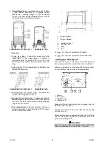
Do not place or operate this machine on a surface
with an incline greater than 15° from horizontal.
Do not use this machine for pipe thawing.
This machine must be located where there is free
circulation of clean air without restrictions for air
movement to and from the air vents. Do not cover
the machine with paper, cloth or rags when switched
on.
Dirt and dust that can be drawn into the machine
should be kept to a minimum.
This machine has a protection rating of IP23. Keep it
dry when possible and do not place it on wet ground
or in puddles.
Locate the machine away from radio controlled
machinery. Normal operation may adversely affect
the operation of nearby radio controlled machinery,
which may result in injury or equipment damage.
Read the section on electromagnetic compatibility in
this manual.
Do not operate in areas with an ambient temperature
greater than 40°C.
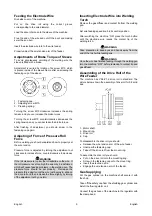
Duty cycle and Overheating
The duty cycle of a welding machine is the percentage of
time in a 10 minute cycle at which the welder can operate
the machine at rated welding current.
20% duty cycle:
Welding for 2 minutes.
Break for 8 minutes.
Excessive extension of the duty cycle will cause the
thermal protection circuit to activate.
The welding transformer in the machine is protected from
overheating by a thermostat. When the machine is
overheated the output of the machine will turn “OFF“, and
the Thermal Indicator Light will turn “ON“. When the
machine has cooled to a safe temperature the Thermal
Indicator Light will go out and the machine may resume
normal operation. Note: For safety reasons the machine
will not come out of thermal shutdown if the trigger on the
welding gun has not been released.
Minutes
or
decrease
duty cycle
Input Supply Connection
Installation and mains outlet socket shall be made and
protected according to appropriate rules.
Check the input voltage, phase, and frequency supplied to
this machine before turning it on. Verify the connection of
grounding wires from the machine to the input source.
The allowable input voltages are 1x230V 50Hz/60Hz. For
more information about input supply refer to the technical
specification section of this manual and to the rating plate
of the machine.
Make sure the amount of power available from the input
connection is adequate for normal operation of the
machine. The necessary delayed fuse (or circuit breaker
with ”D” characteristic) and cable sizes are indicated in the
technical specification section of this manual.
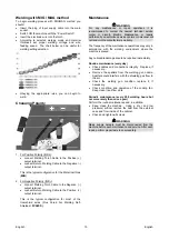
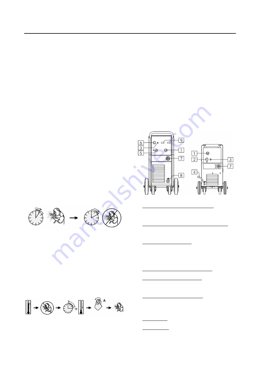
Controls and Operational Features
POWERTEC 191C/231C/271C
POWERTEC 161C
1. WFS (Wire Feed Speed) Control Knob: It enables
continuous control of wire feeding speed in the range
from 1.0 to 20m/min.
2. Power and Welding Voltage Changing Switch: It
enables to turn the machine ON and switching the
voltage. The POWERTEC 161C has a 7-steps switch.
3. Thermal Overload Indicator: This lamp will light up
when the machine is overheated and the output has
been turned off. Leave the machine on to allow the
internal components to cool, when the lamp turns off
normal operation is possible.
4. Return Welding Cable Fixed With Clamp.
5. Welding Voltage Changing Switch: The POWERTEC
191C has a 8-steps switch. The POWERTEC 231C
and 271C have a 12-steps switch.
6. Power Switch and Power Indicator: After input power
is connected and the power switch is turned on, the
indicator will light up to indicate the machine is ready
to weld.
7. EURO Socket: For connecting welding torch.
8. Output Socket: For connecting the return welding
cable.


