background image

– 4 –

PRÉCAUTIONS DE SÛRETÉ

Pour votre propre protection lire et observer toutes les instructions

et les précautions de sûreté specifiques qui parraissent dans ce

manuel aussi bien que les précautions de sûreté générales suiv-

antes:

Sûreté Pour Soudage A L’Arc

1.  Protegez-vous contre la secousse électrique:

a. Les circuits à l’électrode et à la piéce sont sous tension

quand la machine à souder est en marche. Eviter toujours

tout contact entre les parties sous tension et la peau nue ou

les vétements mouillés. Porter des gants secs et sans trous

pour isoler les mains.

b. Faire trés attention de bien s’isoler de la masse quand on

soude dans des endroits humides, ou sur un plancher met-

allique ou des grilles metalliques, principalement dans 

les positions assis ou couché pour lesquelles une grande 

partie du corps peut être en contact avec la masse.

c. Maintenir le porte-électrode, la pince de masse, le câble de

soudage et la machine à souder en bon et sûr état defonc-

tionnement.

d.Ne jamais plonger le porte-électrode dans l’eau pour le

refroidir.

e. Ne jamais toucher simultanément les parties sous tension

des porte-électrodes connectés à deux machines à souder 

parce que la tension entre les deux pinces peut être le total 

de la tension à vide des deux machines.

f. Si on utilise la machine à souder comme une source de

courant pour soudage semi-automatique, ces precautions

pour le porte-électrode s’applicuent aussi au pistolet de

soudage.

2.  Dans le cas de travail au dessus du niveau du sol, se protéger

contre les chutes dans le cas ou on recoit un choc. Ne jamais

enrouler le câble-électrode autour de n’importe quelle partie du

corps.

3.  Un coup d’arc peut être plus sévère qu’un coup de soliel, donc:

a. Utiliser un bon masque avec un verre filtrant approprié ainsi

qu’un verre blanc afin de se protéger les yeux du rayon-

nement de l’arc et des projections quand on soude ou

quand on regarde l’arc.

b. Porter des vêtements convenables afin de protéger la peau

de soudeur et des aides contre le rayonnement de l‘arc.

c. Protéger l’autre personnel travaillant à proximité au

soudage à l’aide d’écrans appropriés et non-inflammables.

4.  Des gouttes de laitier en fusion sont émises de l’arc de

soudage. Se protéger avec des vêtements de protection libres

de l’huile, tels que les gants en cuir, chemise épaisse, pan-

talons sans revers, et chaussures montantes.

5.  Toujours porter des lunettes de sécurité dans la zone de

soudage. Utiliser des lunettes avec écrans lateraux dans les

zones où l’on pique le laitier.

6.  Eloigner les matériaux inflammables ou les recouvrir afin de

prévenir tout risque d’incendie dû aux étincelles.

7.  Quand on ne soude pas, poser la pince à une endroit isolé de

la masse. Un court-circuit accidental peut provoquer un échauf-

fement et un risque d’incendie.

8.  S’assurer que la masse est connectée le plus prés possible de

la zone de travail qu’il est pratique de le faire. Si on place la

masse sur la charpente de la construction ou d’autres endroits

éloignés de la zone de travail, on augmente le risque de voir

passer le courant de soudage par les chaines de levage,

câbles de grue, ou autres circuits. Cela peut provoquer des

risques d’incendie ou d’echauffement des chaines et des

câbles jusqu’à ce qu’ils se rompent.

9.  Assurer une ventilation suffisante dans la zone de soudage.

Ceci est particuliérement important pour le soudage de tôles

galvanisées plombées, ou cadmiées ou tout autre métal qui

produit des fumeés toxiques.

10. Ne pas souder en présence de vapeurs de chlore provenant

d’opérations de dégraissage, nettoyage ou pistolage. La

chaleur ou les rayons de l’arc peuvent réagir avec les vapeurs

du solvant pour produire du phosgéne (gas fortement toxique)

ou autres produits irritants.

11. Pour obtenir de plus amples renseignements sur la sûreté, voir

le code “Code for safety in welding and cutting” CSA Standard

W 117.2-1974.

PRÉCAUTIONS DE SÛRETÉ POUR
LES MACHINES À SOUDER À
TRANSFORMATEUR ET À
REDRESSEUR

1.  Relier à la terre le chassis du poste conformement au code de

l’électricité et aux recommendations du fabricant. Le dispositif

de montage ou la piece à souder doit être branché à une

bonne mise à la terre.

2.  Autant que possible, I’installation et l’entretien du poste seront

effectués par un électricien qualifié.

3.  Avant de faires des travaux à l’interieur de poste, la debrancher

à l’interrupteur à la boite de fusibles.

4.  Garder tous les couvercles et dispositifs de sûreté à leur place.

Mar. ‘93

Summary of Contents for PRO-CUT 60

Page 1: ...r installation and thought ful operation on your part DO NOT INSTALL OPERATE OR REPAIR THIS EQUIPMENT WITHOUT READING THIS MANUAL AND THE SAFETY PRECAUTIONS CONTAINED THROUGHOUT And most importantly think before you act and be careful R Sales and Service through Subsidiaries and Distributors Worldwide Cleveland Ohio 44117 1199 U S A TEL 216 481 8100 FAX 216 486 1751 WEB SITE www lincolnelectric co...

Page 2: ...t spatter or metal ELECTRIC SHOCK can kill 1 a The electrode and work or ground circuits are electrically hot when the power source is on Do not touch these hot parts with your bare skin or wet clothing Wear dry hole free gloves to insulate hands 1 b When the power source is operating voltages in excess of 250 volts are produced This creates the potential for serious electrical shock potentially e...

Page 3: ...localized Electric and Magnetic Fields EMF Cutting or gouging current creates EMF fields around torch cables and cutting machines 8 b EMF fields may interfere with some pacemakers so opera tors having a pacemaker should consult their physician before cutting or gouging 8 c Exposure to EMF fields during cutting or gouging may have other health effects which are now not known 8d All operators should...

Page 4: ... non inflammables 4 Des gouttes de laitier en fusion sont émises de l arc de soudage Se protéger avec des vêtements de protection libres de l huile tels que les gants en cuir chemise épaisse pan talons sans revers et chaussures montantes 5 Toujours porter des lunettes de sécurité dans la zone de soudage Utiliser des lunettes avec écrans lateraux dans les zones où l on pique le laitier 6 Eloigner l...

Page 5: ...ion 11 Operating Instructions 11 14 Sequence of events 11 Pilot Arc Discussion 12 Procedure Recommendations 12 General 12 Thin Gauge Sheet Metal 12 Expanded Metal 13 Thick Sections of Metal 13 Gouging 13 In All Cases 14 Suggestions for Extra Utility from the PRO CUT System 14 Maintenance Procedures 15 Routine Maintenance 15 Troubleshooting Procedures 15 21 Troubleshooting Guide 15 18 PRO CUT 60 St...

Page 6: ...re the information must be followed to avoid minor personal injury or damage to this equipment CAUTION Please Examine Carton and Equipment For Damage Immediately When this equipment is shipped title passes to the purchaser upon receipt by the carrier Consequently Claims for material damaged in shipment must be made by the purchaser against the transportation company at the time the shipment is rec...

Page 7: ...Magnum PCT 60 Air Cooled Torch Input Frequency 60 Hz Output Rating 60 Amps 115 volts 60 Duty Cycle 60 Amps 115 volts Maximum Output 45 Amps 115 volts 100 Duty Cycle Pilot Current 22 5 amps Pilot Duty Cycle 25 20 seconds out of 80 seconds Current Range 25 60 Amps Maximum OCV 282 Volts Normal OCV 250 Volts Input Power Standard Voltages 208 230 460 1 60 K1362 1 2 5 6 Current 50 45 23 Amps Other Volta...

Page 8: ...reheat temperature control is recommended for opti mum mechanical properties crack resistance and hardness control This is particularly important on high alloy steels and heat treated aluminum Job con ditions prevailing codes alloy level and other consid erations may also require preheat temperature con trol The following minimum preheat temperature is recommended as a starting point Higher temper...

Page 9: ...ult in excessive operating temperatures or damage to the torch HIGH FREQUENCY INTERFERENCE PROTECTION Since the spark gap oscillator in the high frequency generator in the machine is similar to a radio transmit ter improper machine installation can result in radio and TV interference or problems with nearby electron ic equipment Radiated interference can develop in the following four ways 1 Direct...

Page 10: ...e machine is to be operated on the lower voltage it must be reconnected according to the instructions on the inside of the removable panel in the center of the rear panel Machine supply line entry provision is next to the removable panel 10 Have a qualified electrician connect the input leads to L1 and L2 of the terminal block in accordance with any National Electrical Code all local codes and the...

Page 11: ...voided Remove the plastic thread protector from the regulator input port located on the back of the machine Use a suitable gas connection fitting to make the connection to the available air supply The input port is a 1 4 6 3 mm NPT thread Tighten the air fitting to prevent leakage but do not overtighten The use of Teflon tape to seal the connection is recommended Nitrogen from cylinders may be use...

Page 12: ...essing the Safety Reset button It is possible for electrical noise to trip the safety cir cuit on rare occasions This should not be a regular occurrence If the machine does not reset or continues to trip consult the Troubleshooting Section Pilot Arc Discussion The PRO CUT has a smooth continuous pilot arc The pilot arc is only a means of transferring the arc to the workpiece for cutting Repeated p...

Page 13: ...aces Thick Sections of Metal Output set above mid range The best quality and consumable life will be obtained by holding the torch nozzle off the sur face about 1 8 3 2mm Output control should be sent in the red range only Do not touch the nozzle to the work or carry a long arc Use the S24114 Drag Cup to protect the torch The only reason not to use the Drag Cup when the output control is in the bl...

Page 14: ...long before a PRO CUT system does This is because of the solid state current regulation that the PRO CUT has Also the safety reset circuit provides a means of extending nozzle life Sometimes a small piece of material breaks off the electrode and bridges the gap between the nozzle and the electrode In a competitive unit this would often result in the destruction of the elec trode and nozzle due to ...

Page 15: ...able periodically and relieve any so as not to restrict the flow of air to the torch ELECTRICAL SHOCK CAN KILL Turn off machine at the disconnect switch at the back of the machine before tightening cleaning or replacing consumables Change consumables as required TROUBLESHOOTING PROCEDURES HOW TO USE THIS GUIDE Carefully read through each applicable section listed on the following pages Remember th...

Page 16: ...o the machine If the air does not flow the machine will not start 4 Check the operation of the air solenoid by switching the machine to PURGE The air should begin to flow and if the pressure is suffi cient the AIR PRESSURE LED will light Return to RUN mode If air does not flow check the solenoid by applying 115 VAC to its input leads If it is bad replace the solenoid or else replace the control bo...

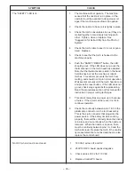
Page 17: ...r replace See Suggestion for Extra Utility from the PRO CUT System 3 Check the torch cab le to see if it is cut or punctured Replace 4 Turn off the machine and turn it back on If the FAULT LED will not stay off when you try to cut again and there is no problem with the torch then something has failed in the machine and the machine should not be left on 4a Check electrode to pilot for short 4b Chec...

Page 18: ...melting and should not trip in normal operation Wait several minutes until the torch head is cool and press the reset button If the LED does not go out check step 2 again before proceeding Read the procedures section of this manual for instruction in proper cutting technique 7 This circuit rarely trips on power up or because of noise If the circuit can be reset it is Ok to continue operation 8 Che...

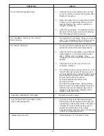
Page 19: ...Check consumables replace as needed checks to see if the torch is shorted and if Check torch cable to see if it is punctured it can fire the transistors or cut Light blinking If cutting tried with air No air connected to machine air pressure pressure less than 60 psi 413 kPa while set too low or air leak in system air is flowing the machine will wait for air pressure to become greater than 60 psi ...

Page 20: ...oving the hafnium that builds up on the inside of the nozzle it is possible to extend the life of the consumables If the cable is punctured or cut it can trip By pressing reset it will clear the SAFETY the SAFETY When cutting is tried again the machine will either go into FAULT or SAFETY until that time the machine will not indicate a malfunction condition The torch may be overheated There is Wait...

Page 21: ...re possibly subjecting the new PC board to the same cause of failure check for possible shorts opens or grounds caused by 1 Frayed or pinched lead insulation 2 Poor lead termination such as a poor contact or a short to adjacent connection or surface 3 Two or more leads shorted together 4 Foreign matter or interference behind the PC boards If PC board is visibly damaged mechanically such as a part ...

Page 22: ...OHM WATT 1 2 WATT UNLESS OTHERWISE SPECIFIED 3 3 75 76 77 304 L501 L502 SPARK GAP C1 319 6J12 3J12 4J12 1J12 3 4 222 221 R 5 L503 L504 N A PILOT LEAD AT THE TORCH NOTES NUMBER 3 IS CONNECTED TO THE NOZZLE H3 H4 H6 MAIN SEC L1 2 1 5 4 1 T1 T2 L1 1 2 1 4 5 T1 T2 TO GROUND PER NATIONAL ELECTRICAL CODE TO PRIMARY COILS S1 TS1 TO SUPPLY LINES L2 2 3 L1 1 2 1 4 5 T1 T2 6 8 7 335 32 31 37 C1 R W 5 10 386...

Page 23: ... GND USE FERRULE 10 AWG ONLY TORQUE TO 16 IN LBS FOR 575 VOLTS 575 V 60HZ 460 V 60HZ 1 0 8 9 3 P INPUT SUPPLY CONNECTION DIAGRAM NOTE MACHINES ARE SHIPPED FROM FACTORY CONNECTED THE LINCOLN ELECTRIC CO CLEVELAND OHIO U S A 2 CONNECT TERMINAL MARKED TO GROUND PER OF THE TERMINAL BLOCK AS SHOWN NATIONAL ELECTRICAL CODE LINK LINK POSITIONS L1 L2 460 V 60HZ FOR 440 OR 460 VOLTS M15698 1 CONNECT L1 L2 ...

Page 24: ...W O R K TM PRO CUT 60 POWER SOURCE PLASMA TORCH FOR MAGNUM PCT 60 2 INSERT TORCH CABLE THROUGH CABLE BOOT TURN AND LOCK STRAIN RELIEF CLAMP ONTO BOLT SCREW TIGHT 5 ATTACH AMPHENOL CONNECTOR 3 CONNECT PILOT LEAD A D A P T E R G A S L I N E B O L T S T R A I N R E L I E F C L A M P C A B L E B O O T W O R K L E A D 7 2 6 9 1 C 1 DISCONNECT INPUT POWER TO THE PRO CUT AND TURN MACHINE POWER SWITCH OFF...

Page 25: ...NOTES ...
Page 26: ...101 A 45 00 SP100 Codes 9284 10050 SVM102 A 45 00 Power Arc 4000 Codes 10083 SVM103 A 45 00 Power Arc 4000 Codes 10200 10244 SVM103 B 45 00 ProCut 60 Single Phase Codes 9819 10118 SVM104 A 45 00 V300 PRO Codes 9934 10131 SVM105 A 45 00 LN 7 GMA Codes 9168 9931 SVM106 A 45 00 RANGER 8 Codes 9972 10110 SVM107 A 45 00 DC600 Codes 9773 9910 SVM108 A 45 00 POWER WAVE 350 500 Codes 10104 10155 SVM109 A ...

Page 27: ...lletin ED 80 or call 216 383 2259 and ask for the Welding School Registrar Lincoln Welding School BASIC COURSE 700 00 5 weeks of fundamentals There is a 10 discount on all orders of 50 00 or more for shipment at one time to one location Orders of 50 or less before discount or orders outside of North America must be prepaid with charge check or money order in U S Funds Only Prices include shipment ...

Page 28: ...electrically live parts or electrode with skin or wet clothing Insulate yourself from work and ground No toque las partes o los electrodos bajo carga con la piel o ropa moja da Aislese del trabajo y de la tierra Ne laissez ni la peau ni des vête ments mouillés entrer en contact avec des pièces sous tension Isolez vous du travail et de la terre Berühren Sie keine stromführenden Teile oder Elektrode...

Page 29: ...gute Be und Entlüftung des Arbeitsplatzes Mantenha seu rosto da fumaça Use ventilação e exhaustão para remover fumo da zona respiratória Turn power off before servicing Desconectar el cable de ali mentación de poder de la máquina antes de iniciar cualquier servicio Débranchez le courant avant l entre tien Strom vor Wartungsarbeiten abschalten Netzstrom völlig öff nen Maschine anhalten Não opere co...

Reviews: