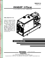
SVM207-A
January, 2011
Safety Depends on You
Lincoln arc welding and cutting
equipment is designed and built
with safety in mind. However,
your overall safety can be
increased by proper installation
. . . and thoughtful operation on
your part. DO NOT INSTALL,
OPERATE OR REPAIR THIS
EQUIPMENT WITHOUT READ-
ING THIS MANUAL AND THE
SAFETY PRECAUTIONS CON-
TAINED THROUGHOUT. And,
most importantly, think before you
act and be careful.
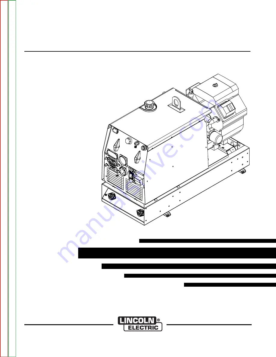
SERVICE MANUAL
For use with machine code number:
11079 & 11419
RANGER
®
3 Phase
• Sales and Service through Subsidiaries and Distributors Worldwide •
Cleveland, Ohio 44117-1199 U.S.A. TEL: 216.481.8100 FAX: 216.486.1751 WEB SITE: www.lincolnelectric.com
• World's Leader in Welding and Cutting Products •
Copyright © Lincoln Global Inc.
Return
to
Master
T
OC
Return
to
Master
T
OC
Return
to
Master
T
OC
Return
to
Master
T
OC
V
iew
Safety
Info
V
iew
Safety
Info
V
iew
Safety
Info
V
iew
Safety
Info


