


WELDING PROBLEMS
Observe Safety Guidelines detailed in the beginning of this manual.
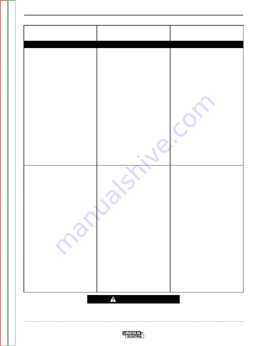
PROBLEMS
(SYMPTOMS)
POSSIBLE AREAS OF
MISADJUSTMENT(S)
RECOMMENDED
COURSE OF ACTION
If for any reason you do not understand the test procedures or are unable to perform the tests/repairs safely,
contact the Lincoln Electric Service Department for technical troubleshooting assistance before you proceed.
Call 1-888-935-3877.
CAUTION
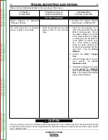
The welding arc is “cold.” Engine
runs normally (3700 RPM no load).
Auxiliary power is functioning nor-
mally.
1. Check for loose or faulty connec-
tions at the weld output terminals
and welding cable connections.
2. The welding cable may be too
long or coiled, causing an exces-
sive voltage drop.
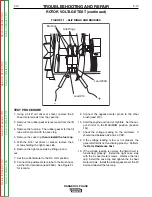
1. Check for the correct open cir-
cuit voltage (OCV) at the welder
output terminals See the
Machine Diagram
. If the cor-
rect voltage is present at the
output terminals, then check for
loose connections on the heavy
current carrying leads inside the
RANGER® 8. See
Wiring
Diagram
.
2. If the OCV is low at the welder
output terminals, perform
The
Engine Throttle Adjustment
Test
.
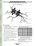
3. Perform the
Output Rectifier
Bridge Test
.
4. Check for shorted or grounded
windings in the reactor and also
in the main stator. See
Wiring
Diagram
.
TROUBLESHOOTING AND REPAIR
F-10
F-10
RANGER® 3 PHASE
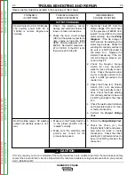
Welding output is low with little
or no control. Auxiliary output is
also low.
1. Check the brushes for wear and
proper contact to the rotor slip
rings.
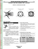
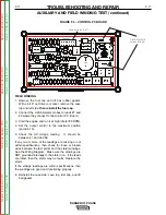
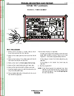
1. Make up a jumper to connect
the Field Test Point (FTP1) on
the PC Board to lead 219. The
connection can be made at the
board (J1,Pin5), or at the
Negative Exciter Brush. See
Figure F.4
and/or the
Wiring
Diagram
. If the output comes
up to full strength, the Control
Board is probably defective.
Replace.
2. Perform the
Rotor Voltage
Test.
3. If Rotor Voltage Test is normal,
then
preform
the
Rotor
Resistance Test.
4. If the Rotor Voltage Test is NOT
normal, perform the
Auxiliary
and Field Winding Voltage
Test.
The Printed Circuit Board
may be faulty. Replace
Return
to
Section
T
OC
Return
to
Section
T
OC
Return
to
Section
T
OC
Return
to
Section
T
OC
Return
to
Master
T
OC
Return
to
Master
T
OC
Return
to
Master
T
OC
Return
to
Master
T
OC


