


TROUBLESHOOTING AND REPAIR
F-30
F-30
RANGER® 3 PHASE
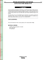
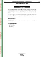
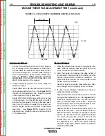
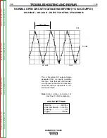
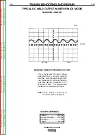
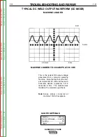
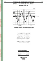
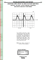
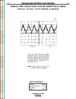
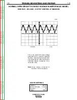
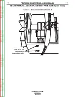
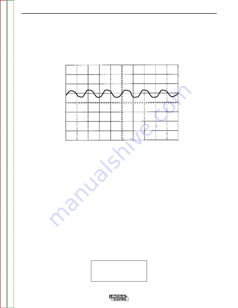
This is the typical CV output voltage
generated from a properly operating
machine. Note that each vertical divi-
sion represents 20 volts and that each
horizontal division represents 5 mil-
liseconds in time. The machine was
loaded with a resistance grid bank.
Note:
Scope probes connected at
machine 115VAC receptacle.
SCOPE SETTINGS
Volts/Div.....................20V/Div.
Horizontal Sweep .....5 ms/Div.
Coupling.............................DC
Trigger.........................Internal
TYPICAL DC WELD OUTPUT WAVEFORM (CV MODE)
MACHINE LOADED
CH1
0 volts
5 ms
20 volts
MACHINE LOADED TO 200 AMPS AT 20 VDC
Return
to
Section
T
OC
Return
to
Section
T
OC
Return
to
Section
T
OC
Return
to
Section
T
OC
Return
to
Master
T
OC
Return
to
Master
T
OC
Return
to
Master
T
OC
Return
to
Master
T
OC


