

IMA 603
REDI-MIG 455 Remote
Page
ACN 000 040 308
THE LINCOLN ELECTRIC COMPANY
(AUSTRALIA) PTY. LTD.
A.B.N. 36 000 040 308
SYDNEY. AUSTRALIA
A Subsidiary of
THE LINCOLN ELECTRIC CO. U.S.A.
Associated Subsidiaries in Australasia, Asia, Europe, North and South America.
THE WORLD’S LEADER IN WELDING AND CUTTING PRODUCTS
SAFETY DEPENDS ON YOU
Lincoln Electric welders are designed and built with safety in mind. However, your overall safety can be increased by
proper installation . . . and thoughtful operation on your part. Read and observe the general safety precautions on
page 2 and follow specific installation and operating instructions included in this manual.
Most importantly, think before you act and be careful.
IMA 603
OPERATING MANUAL
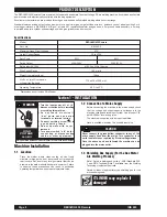
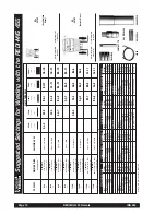
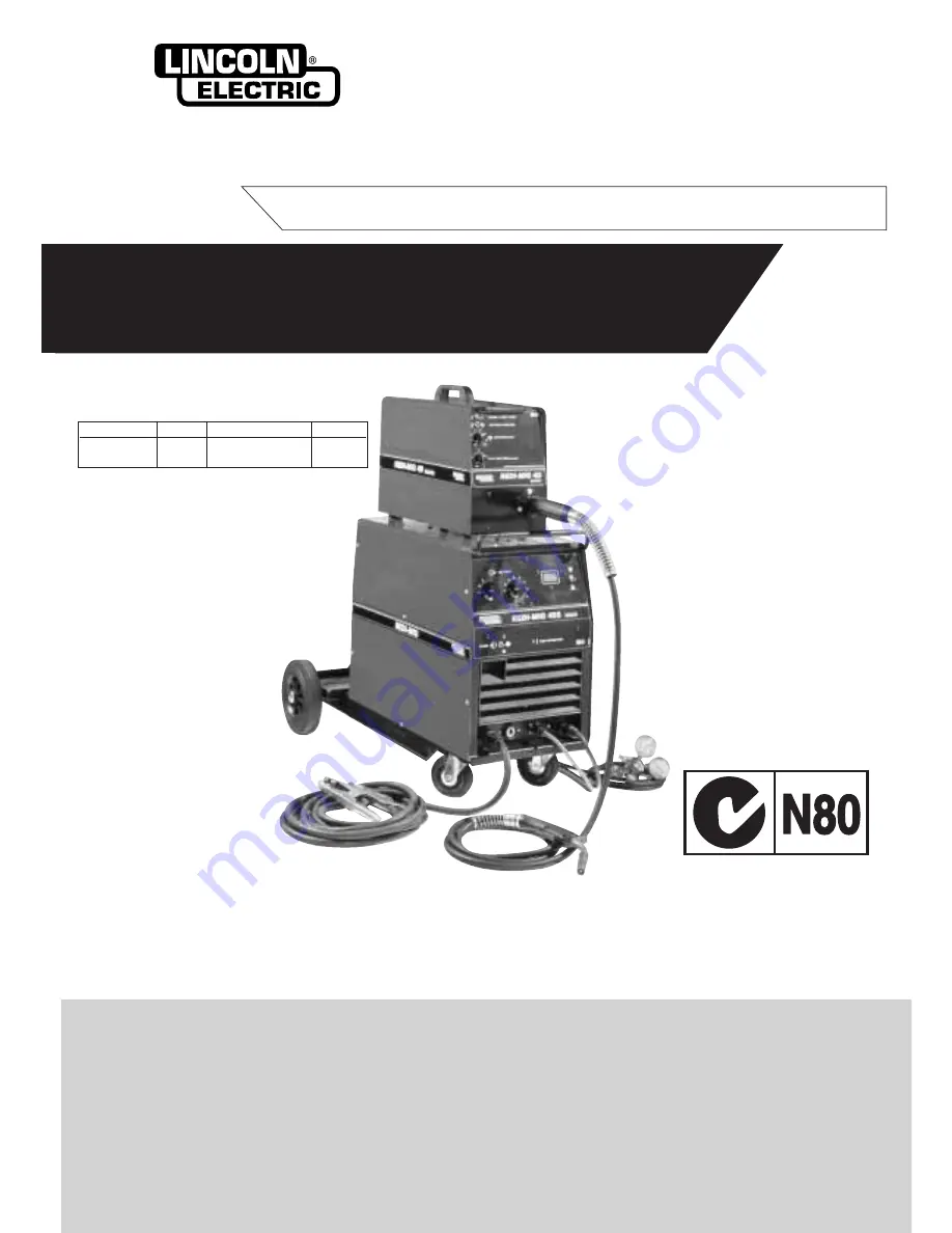
Part No.
Code
Description
Volts
KA1443-2
F948
REDI-MIG 455
415
Remote
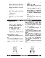
This manual applies to
REDI-MIG 455 Remote
Semi Automatic Arc Welding Machine
EMC Compliant


