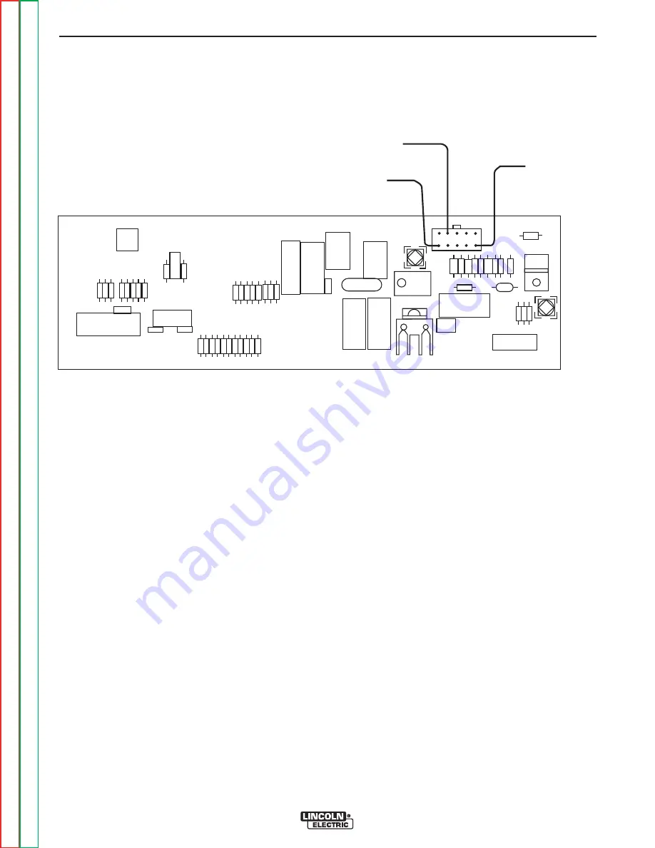
J1-5 (-), CHASSIS
GROUND
J1-9 (+), 11 TO 13 VOLTS
TO FUEL SOLENOIDS
J1-1 (+), BATTERY
VOLTAGE INPUT TO
PC BOARD
FIGURE F.27 – PC BOARD
ENGINE FUEL SYSTEM VOLTAGE TESTS (continued)
PROCEDURE
1. Open the doors on the SAE-400 machine.
WARNING:
Secure the doors in the open position
using the door restraint system. If the
machine does not have a door restraint
system, remove the doors or securely
restrain them to prevent them from falling
closed.
2.
Check the wiring and connections on the
Idle/Engine protection PC board, the engine fuel
system injection pump solenoids, the fuel system
temperature switch, (The fuel pump for Codes
11199 & 11408), and chassis ground. Look for dirty,
corroded, or damaged terminals, including the
Molex terminals connecting the wiring to the PC
board. Look for poor crimp connections and dam-
aged wiring.
3. Make sure the batteries are in good condition, and
are fully charged, then place the run/stop switch in
the run position. Within 30 seconds, check for bat-
tery voltage (11 to 13 VDC), across the primary and
secondary fuel solenoids, (and the fuel pump for
Codes 11199 & 11408). See the wiring diagram.
NOTE:
The secondary solenoid will only have voltage
if the fuel system temperature switch is closed.
Consult a Perkins engine service facility for
precise information about the temperature
switch and other fuel system electrical compo-
nents.
If battery voltage is present at the solenoids and the
fuel pump (If equipped), and the starter motor is crank-
ing the engine normally, the problem is likely in the
engine. Engine problems should be diagnosed and
repaired by a qualified Perkins engine technician.
If battery voltage is not present at the solenoids and
fuel pump (if equipped) follow the procedures below.
TROUBLESHOOTING AND REPAIR
F-74
F-74
SAE-400 SEVERE DUTY
Return to Section
T
OC
Return to Section
T
OC
Return to Section
T
OC
Return to Section
T
OC
Return to Master
T
OC
Return to Master
T
OC
Return to Master
T
OC
Return to Master
T
OC


