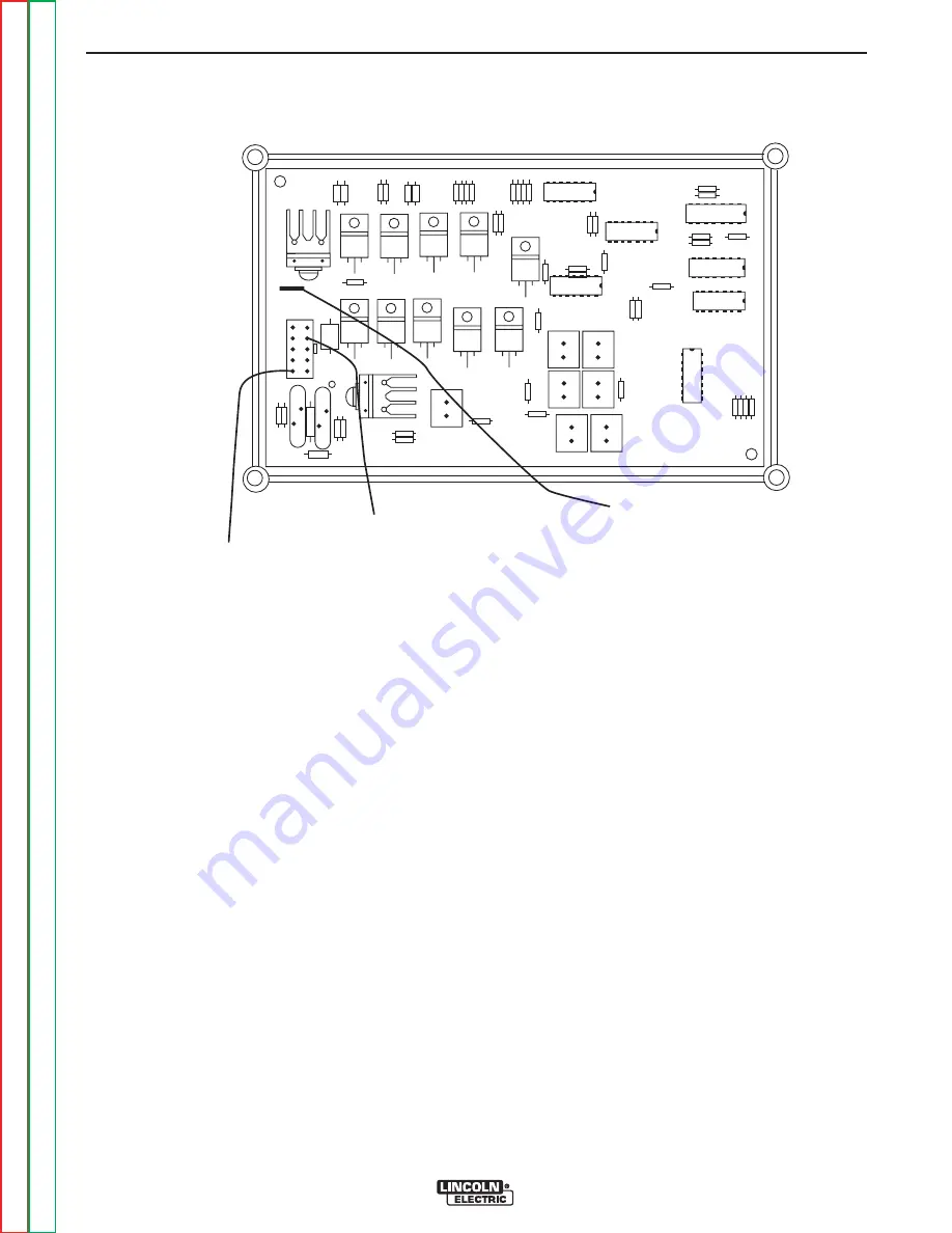
J31-1, (+) BATTERY VOLTAGE
I
NPUT
J31-9 (+) OUTPUT TO FUEL SOLENO
I
DS
AND PUMP
B-1 (-) CHASS
I
S GROUND
FIGURE F.28 – PC BOARD
ENGINE FUEL SYSTEM VOLTAGE TESTS (continued)
PROCEDURE
For Code 10856:
1.
Place the run/stop switch in the “RUN” position and
within 30 seconds, check for battery voltage
between terminal J1-9 (+) and terminal J1-5 (-).
See Figure #1.
2.
Check for battery voltage between terminal J1-1
(+) and terminal J1-5 (-).
If the correct voltage is present for both tests, check the
wiring and connections between the PC board and fuel
system solenoids and temperature switch. Check the
wiring and connections between the solenoids and
chassis ground. See the wiring diagram.
If no voltage is present for either test, check the
run/stop switch and all wiring and connections between
terminal J1-1 and the positive battery terminal. Check
all the wiring and connections between J1-5 and the
negative battery terminal. See wiring diagram.
If the correct voltage is present for test #2, but not for
test #1, and the voltage reading was taken within 30
seconds of placing the run/stop switch in the “run” posi-
tion, The PC board is faulty and should be replaced.
IMPORTANT:
If the PC board is defective, test the
solenoids and engine temperature
switch as follows, before installing the
new PC board.
3. Disconnect both solenoids and the engine tempera-
ture switch, and then check the resistance across
each solenoid. See the machine schematic for
approximate resistance values. Check the resis-
tance between each solenoid and chassis ground,
and between the engine temperature switch and
chassis ground. The resistance should be very
high, 500,000 (500k) Ohms minimum. A qualified
Perkins engine technician should repair or replace
any defective components before a new PC board
is installed.
TROUBLESHOOTING AND REPAIR
F-75
F-75
SAE-400 SEVERE DUTY
Return to Section
T
OC
Return to Section
T
OC
Return to Section
T
OC
Return to Section
T
OC
Return to Master
T
OC
Return to Master
T
OC
Return to Master
T
OC
Return to Master
T
OC


