THEORY OF OPERATION
E-4
E-4
SAE-400 SEVERE DUTY
Return to Section
T
OC
Return to Section
T
OC
Return to Section
T
OC
Return to Section
T
OC
Return to Master
T
OC
Return to Master
T
OC
Return to Master
T
OC
Return to Master
T
OC
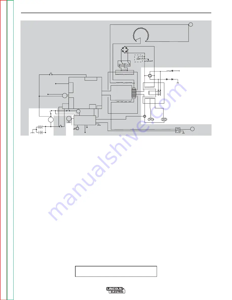
EXCITER/AUXILIARY ALTERNATOR
OPERATION
The exciter alternator is the smaller power generator
that is located at the end of the main welding genera-
tor. It provides power to energize the rotor, the shunt
fields of the main welding generator and about 3 KVA
of 120/230 volts, 60 Hz. for auxiliary power.
Flashing:
The exciter alternator requires that DC power be
applied to the slip rings to start the power generation
process. This DC power is often referred to as
“Flashing” voltage, and originates at the battery. This
voltage is applied through the Idler/Engine Protection
PC Board, whenever the fuel solenoid is open and the
hour meter is running.
The flashing current passes through a blocking diode
and current limiting resistor before being applied to the
rotor field winding through the positive brush and slip
ring. The current then passes out of the negative slip
ring and brush, through two diodes, and back to the
battery through a chassis ground connection.
FIGURE E.2 - GENERAL DESCRIPTION
Building output:
The flashing current produces a weak magnetic field in
the rotor, which is coupled to the now running engine.
This rotating magnetic field begins to generate AC out-
put from all of the stator windings. Output from the
exciter winding is rectified by a diode bridge, and then
fed back into the rotating field winding, through the
brushes, making the magnetic field stronger. This
stronger magnetic field then produces higher voltage
from the stator windings, which feeds back to the rotor,
making its magnetic field even stronger.
This process of strengthening the magnetic field
through feedback from the exciter winding continues to
increase the output of the alternator until the design
voltage is reached.
The field voltage is now considerably higher than the
flashing voltage that was used to start the generating
process. The diode in the flashing circuit now blocks
that higher field voltage from intruding into the 12VDC
battery system and the machine chassis.
(continued on next page)
DIESEL
ENGINE
THERMOSTAT
INJECTION
PUMP
SOLENOID
SYSTEM
THERMOSTART
BUTTON
IDLE SWITCH
IDLE
SOLENOID
IDLE / ENGINE
PROTECTION BOARD
TO IDLE / ENGINE
PROTECTION BOARD
RUN/STOP
SWITCH
S
T
A
R
T
E
R
TO IDLE/ENGINE
PROT. BOARD
OIL
PRESSURE
SWITCH
TEMP
SWITCH
STARTER
SOLENOID
AMMETER
START
BUTTON
ENGINE
FAULT
LIGHT
HOUR
METER
TO
FLASHING
RESISTOR
AND
DIODE
INTERPOLE COILS
GENERATOR
ARMATURE
SERIES COILS
SHUNT COILS
115 VAC
RECEPTACLES
230 VAC
RECEPTACLES
AUXILIARY
POWER
WINDINGS
EXCITER
WINDING
EXCITER
ROTOR
MIN
(OFF)
MAX
OUTPUT
CONTROL
ELECTRODE
TERMINAL
RESISTOR
POLARITY
SWITCH
REMOTE
RHEOSTAT
LOCAL
RHEOSTAT
(JOB SELECTOR)
TO HOUR METER
FLASHING
RESISTOR AND
DIODE
(+)
(+)
(-)
(-)
AC
AC
(-)
(+)
WORK
TERMINAL
TO ALTERNATOR
FLASH/SENSE
TO INJECTION
PUMP SOLENOID
NOTE: Unshaded areas of Block Logic
Diagram are the subject of discussion


