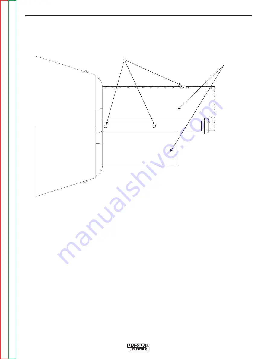
EXC
I
TER COVER
F
I
VE SCREWS
(TWO ON OTHER S
I
DE)
FIGURE F.8 – EXCITER COVER SCREW LOCATIONS
EXCITER ROTOR RESISTANCE AND GROUND TEST
(Exciter / Auxiliary Power Alternator) (continued)
PROCEDURE
“Static” Tests:
1. Turn the engine off.
2. Open either, or both of the doors on the control
panel end of the SAE-400 machine.
WARNING:
Secure the doors in the open position
using the door restraint system. If the
machine does not have a door restraint
system, remove the doors or securely
restrain them to prevent them from falling
closed.
3. Remove the cover from the exciter / auxiliary power
alternator by removing the screws securing it. See
Figure F.8.
4. Locate and label the leads connected to the rotor
brush holder assembly. Remove the leads.to elec-
trically isolate the rotor windings.
TROUBLESHOOTING AND REPAIR
F-34
F-34
SAE-400 SEVERE DUTY
Return to Section
T
OC
Return to Section
T
OC
Return to Section
T
OC
Return to Section
T
OC
Return to Master
T
OC
Return to Master
T
OC
Return to Master
T
OC
Return to Master
T
OC


