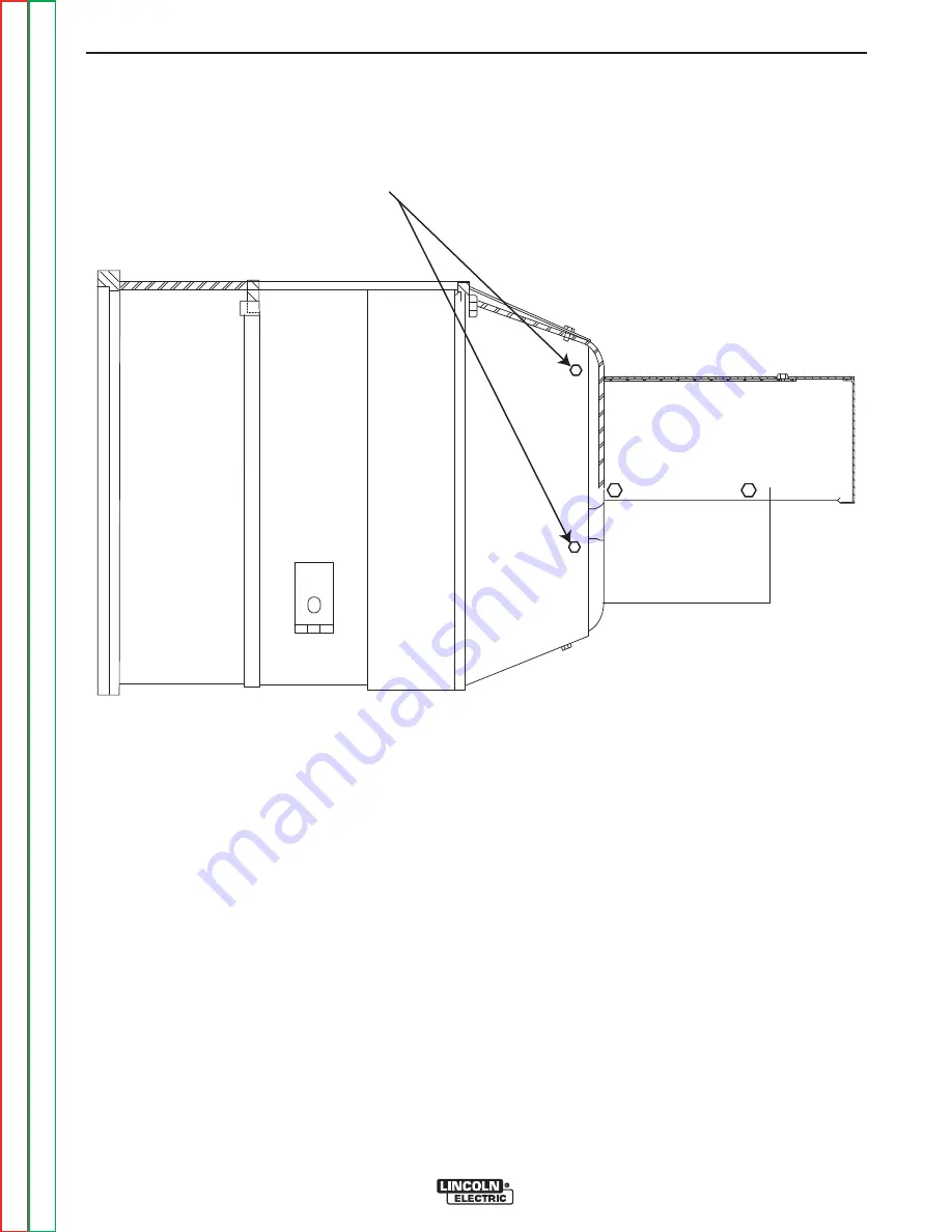
GENERATOR COVER
FOUR SCREWS TOTAL
FIGURE F.15 – GENERATOR COVER SCREW LOCATIONS
WELDING GENERATOR BRUSH AND COMMUTATOR INSPECTION AND
SERVICE (continued)
PROCEDURE
1. Shut off the engine.
2. Open either, or both of the doors on the control
panel end of the SAE-400 machine.
WARNING:
Secure the doors in the open position
using the door restraint system. If the
machine does not have a door restraint
system, remove the doors or securely
restrain them to prevent them from falling
closed.
3. Disconnect the negative battery cable.
4. Remove the sheet metal covers protecting the
welder generator brushes. See Figure F.15.
TROUBLESHOOTING AND REPAIR
F-44
F-44
SAE-400 SEVERE DUTY
Return to Section
T
OC
Return to Section
T
OC
Return to Section
T
OC
Return to Section
T
OC
Return to Master
T
OC
Return to Master
T
OC
Return to Master
T
OC
Return to Master
T
OC


