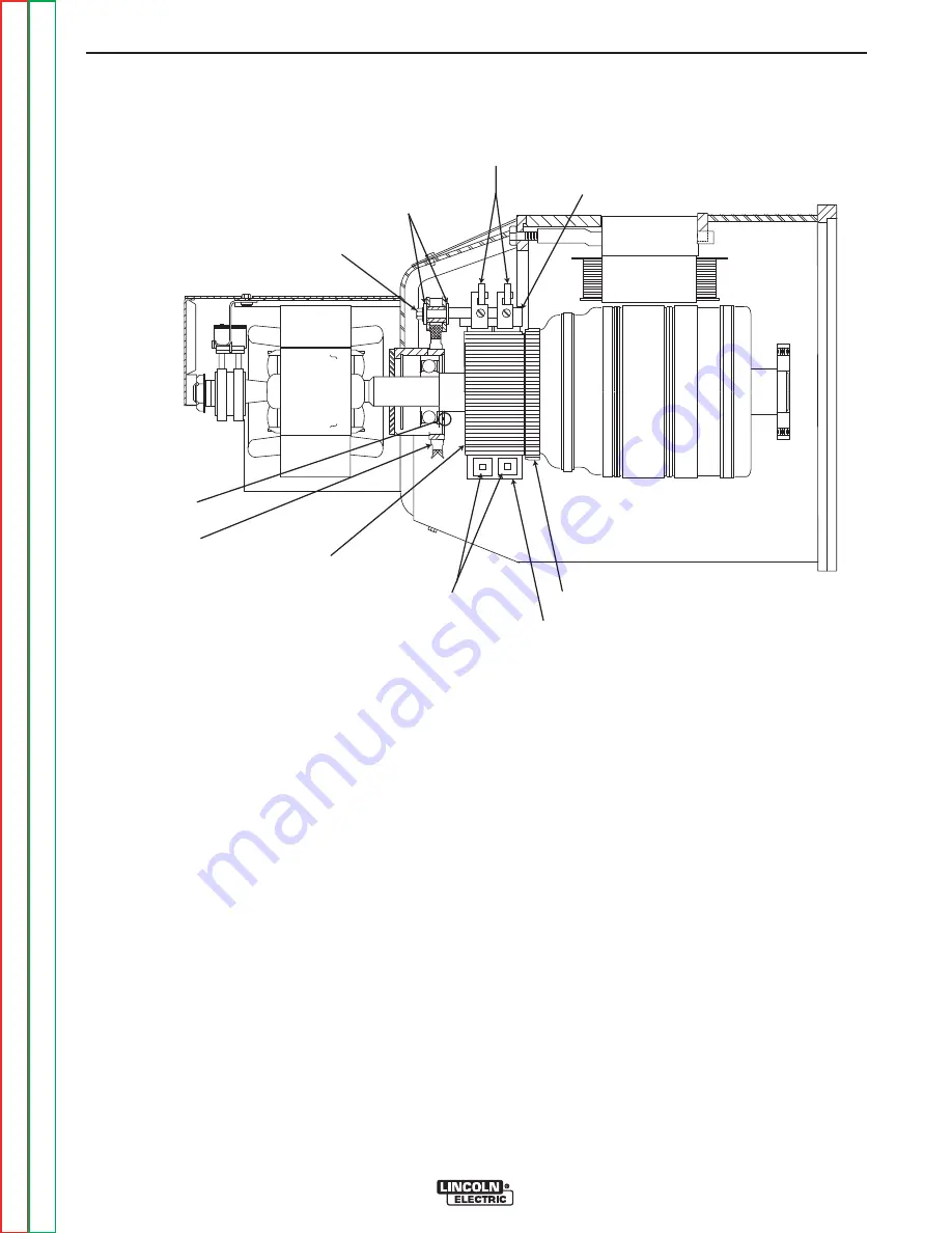
ARMATURE
COMMUTATOR
SPRINGS
BRUSH HOLDER PLATE
BRUSHES
BRUSH RETAINER
BRUSH HOLDER
INSULATORS
MOUNTING SCREW
DRILL MARK
ROCKER
FIGURE F.16 – GENERATOR COMPONENTS
WELDING GENERATOR BRUSH AND COMMUTATOR INSPECTION AND
SERVICE (continued)
PROCEDURE
5. Examine the Commutator.
Normal appearance:
The commutator should appear smooth, and have an
even brown color where the brushes ride.
Blackened Commutator:
A commutator that appears to have an even black color
all around may indicate a grounded armature, shorted
weld circuit, a serious overload condition, or out-of-
adjustment rocker. It could also indicate the use of
poor quality brushes, or brushes that have been conta-
minated with oil or some other foreign substance.
•
Check the rocker position. Be certain that it is
aligned with or very close to the factory drill mark.
See Figure 16. IMPORTANT: If the rocker position
requires adjustment, do not over tighten the rocker
clamping screw. This screw should be tightened to
a torque of 70 to 75 Inch-Lbs. Over tightening can
destroy the rocker.
•
Perform the
Weld Circuit Ground and Short
Circuit Test
.
•
If the weld circuit is not grounded or shorted, and
poor brush quality or contamination is suspected,
replace the brushes and seat them with a commu-
tator stone or sand paper.
•
If brush quality or contamination is not suspected,
clean the commutator by lightly stoning the sur-
face.
CAUTION:
Stoning the commutator involves pressing
an abrasive stone against a spinning com-
mutator. This procedure can be haz-
ardous if done without proper training,
tools and protective equipment. Consult
the commutator stone manufacturer’s
instructions before attempting this proce-
dure.
TROUBLESHOOTING AND REPAIR
F-45
F-45
SAE-400 SEVERE DUTY
Return to Section
T
OC
Return to Section
T
OC
Return to Section
T
OC
Return to Section
T
OC
Return to Master
T
OC
Return to Master
T
OC
Return to Master
T
OC
Return to Master
T
OC


