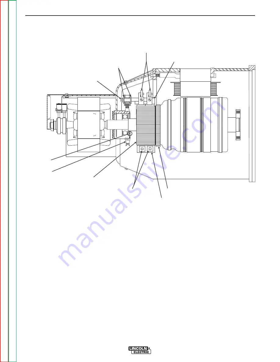
ARMATURE
COMMUTATOR
SPRINGS
BRUSH HOLDER PLATE
BRUSHES
BRUSH RETAINER
BRUSH HOLDER
INSULATORS
MOUNTING SCREW
DRILL MARK
ROCKER
FIGURE F.18 – ROCKER W/MARKS
ROCKER ADJUSTMENT PROCEDURE (continued)
PROCEDURE
The factory set point drill marks:
1. When the rocker is set for the first time at the facto-
ry, a 1/8” drill is used to mark the position of both the
rocker and the exciter bracket. See Figure F.18
If a machine is not operating within the specified limits,
and nothing else appears to be faulty, the rocker posi-
tion should be checked. If the drill marks are not
aligned, the rocker and/or the exciter bracket should be
reset to the original factory position.
If it has been determined that a rocker adjustment is
necessary on an unaltered machine; the rocker should
only be moved in very small increments, and the total
movement should be no more than ½ the diameter of
the drill mark.
Setting the Rocker -
if the factory drill mark is miss-
ing or invalid due to component replacement.
IMPORTANT:
The following procedures should only be
attempted if all the other systems have
been thoroughly checked and are func-
tioning normally.
A tachometer will be required for this phase of the test.
See the
Engine RPM Adjustment Tes
t for details
about measuring engine RPM.
TROUBLESHOOTING AND REPAIR
F-56
F-56
SAE-400 SEVERE DUTY
Return to Section
T
OC
Return to Section
T
OC
Return to Section
T
OC
Return to Section
T
OC
Return to Master
T
OC
Return to Master
T
OC
Return to Master
T
OC
Return to Master
T
OC


