background image

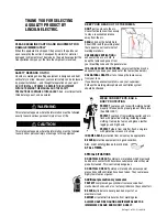
THANK YOU FOR SELECTING 

A QUALITY PRODUCT BY 

LINCOLN  ELEC  TRIC. 

PLEASE EXAMINE CARTON AND EQUIPMENT FOR
DAMAGE IMMEDIATELY

When this equipment is shipped, title passes to the purchaser
upon receipt by the carrier. Consequently, claims for material
damaged in shipment must be made by the purchaser against the
transportation company at the time the shipment is received.

SAFETY DEPENDS ON YOU

Lincoln arc welding and cutting equipment is designed and built
with safety in mind. However, your overall safety can be increased
by proper installation ... and thoughtful operation on your part. 

DO NOT INSTALL, OPERATE OR REPAIR THIS EQUIPMENT 

WITHOUT READING THIS MANUAL AND THE SAFETY

PRECAUTIONS CONTAINED THROUGHOUT.

And, most importantly,

think before you act and be careful.

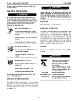
This statement appears where the information must be followed
exactly to avoid serious personal injury or loss of life.

This statement appears where the information must be followed
to avoid minor personal injury or damage to this equipment.

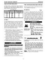
KEEP YOUR HEAD OUT OF THE FUMES.

DON’T

get too close to the arc.

Use corrective lenses if necessary
to stay a reasonable distance
away from the arc.

READ

and obey the Safety Data

Sheet (SDS) and the warning label
that appears on all containers of
welding materials.

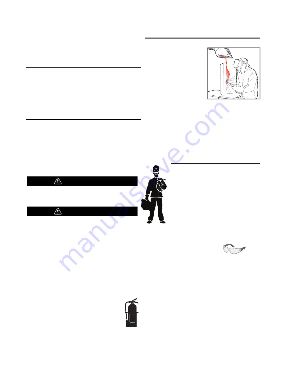
USE ENOUGH VENTILATION

or

exhaust at the arc, or both, to
keep the fumes and gases from 
your breathing zone and the general area.

IN A LARGE ROOM OR OUTDOORS

, natural ventilation may be

adequate if you keep your head out of the fumes (See below).

USE NATURAL DRAFTS

or fans to keep the fumes away 

from your face.

If you de velop unusual symptoms, see your supervisor. 
Perhaps the welding atmosphere and ventilation system 
should be checked.

WEAR CORRECT EYE, EAR & 
BODY PROTECTION

PROTECT

your eyes and face with welding helmet

properly fitted and with proper grade of filter plate
(See ANSI Z49.1).

PROTECT

your body from welding spatter and arc

flash with protective clothing including woolen
clothing, flame-proof apron and gloves, leather
leggings, and high boots.

PROTECT

others from splatter, flash, and glare

with protective screens or barriers.

IN SOME AREAS

, protection from noise may be appropriate.

BE SURE

protective equipment is in good condition.

Also, wear safety glasses in work area

AT ALL TIMES.

SPECIAL SITUATIONS

DO NOT WELD OR CUT

containers or materials which previously

had been in contact with hazardous substances unless they are
properly cleaned. This is extremely dangerous.

DO NOT WELD OR CUT

painted or plated parts unless special

precautions with ventilation have been taken. They can release
highly toxic fumes or gases.

Additional precautionary measures

PROTECT

compressed gas cylinders from excessive heat,

mechanical shocks, and arcs; fasten cylinders so they cannot fall.

BE SURE

cylinders are never grounded or part of an 

electrical circuit.

REMOVE 

all potential fire hazards from welding area.

ALWAYS HAVE FIRE FIGHTING EQUIPMENT READY FOR

IMMEDIATE USE AND KNOW HOW TO USE IT.

WARNING

CAUTION

Safety 01 of 04 - 5/16/2018

Summary of Contents for SAE-500

Page 1: ... use with machines having Code Numbers 12241 12242 12687 12688 Save for future reference Date Purchased Code ex 10859 Serial ex U1060512345 Need Help Call 1 888 935 3877 to talk to a Service Representative Hours of Operation 8 00 AM to 6 00 PM ET Mon thru Fri After hours Use Ask the Experts at lincolnelectric com A Lincoln Service Representative will contact you no later than the following busines...

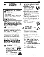
Page 2: ...N A LARGE ROOM OR OUTDOORS natural ventilation may be adequate if you keep your head out of the fumes See below USE NATURAL DRAFTS or fans to keep the fumes away from your face If you develop unusual symptoms see your supervisor Perhaps the welding atmosphere and ventilation system should be checked WEAR CORRECT EYE EAR BODY PROTECTION PROTECT your eyes and face with welding helmet properly fitted...

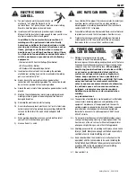
Page 3: ... hot engine parts and igniting Do not spill fuel when filling tank If fuel is spilled wipe it up and do not start engine until fumes have been eliminated 1 d Keep all equipment safety guards covers and devices in position and in good repair Keep hands hair clothing and tools away from V belts gears fans and all other moving parts when starting operating or repairing equipment 1 e In some cases it ...

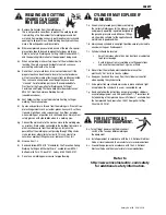
Page 4: ...rm to ANSI Z87 I standards 4 b Use suitable clothing made from durable flame resistant material to protect your skin and that of your helpers from the arc rays 4 c Protect other nearby personnel with suitable non flammable screening and or warn them not to watch the arc nor expose themselves to the arc rays or to hot spatter or metal FUMES AND GASES CAN BE DANGEROUS 5 a Welding may produce fumes a...

Page 5: ...ent passing through lifting chains crane cables or other alternate circuits This can create fire hazards or overheat lifting chains or cables until they fail 6 h Also see item 1 c 6 I Read and follow NFPA 51B Standard for Fire Prevention During Welding Cutting and Other Hot Work available from NFPA 1 Batterymarch Park PO box 9101 Quincy MA 022690 9101 6 j Do not use a welding power source for pipe...

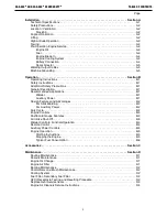
Page 6: ...tures and Advantages B 2 For Stick Welding B 2 For Auxiliary Power B 2 Duty Cycle B 2 Engine Controls B 3 Dashboard Gauge Features B 3 Air Intake Shut Off B 3 Welder Controls Function Operation B 4 Remote Control B 4 Auxiliary Power Controls B 4 Engine Operation B 5 Starting Instructions B 5 Stopping the Engine B 5 Typical Fuel Consumption B 6 Accessories Section C Maintenance Section D Routine Ma...

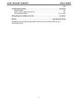
Page 7: ...afety Warning E 1 How To Use Troubleshooting Guide E 1 Troubleshooting Guide E 2 thru E 5 Wiring Diagram and Dimension Print Section F Parts List parts lincolnelectric com Content details may be changed or updated without notice For most current Instruction Manuals go to parts lincolnelectric com ...

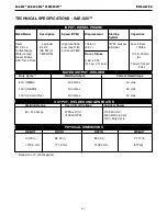
Page 8: ... Diesel Engine 8 L EPA Tier 4 Final 3 62 x 4 33 92 0 mm x 110 0mm Coolant 2 40 gal 9 06 L INPUT DIESEL ENGINE RATED OUTPUT WELDER HEIGHT WIDTH DEPTH WEIGHT 50 13 in 28 00 in 83 00 in 2 111 lb 1273 3 mm 711 2 mm 2108 2 mm 957kg OUTPUT WELDER AND GENERATOR Duty Cycle 1 Welding Output Volts at Rated Amps 60 NEMA 500 amps 40 volts 100 NEMA 400 amps 36 volts 100 Lincoln Plus 400 amps 40 volts Welding R...

Page 9: ...the engine exhaust fumes are properly vented to an outside area DO NOT MOUNT OVER COMBUSTIBLE SURFACES Where there is a combustible surface directly under stationary or fixed electrical equipment that surface shall be covered with a steel plate at least 06 1 6mm thick which shall extend not less than 5 90 150mm beyond the equipment on all sides STACKING These machines cannot be stacked ANGLE OF OP...

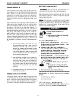
Page 10: ...po nents such as suspension axles and tires Mount equipment base to metal bed or frame of vehicle Follow vehicle manufacturer s instruction WARNING PRE OPERATION ENGINE SERVICE READ the engine operating and maintenance instruc tions supplied with this machine ENGINE OIL The engine is shipped with the engine crankcase filled with high quality SAE 10W 40 FE oil API class CD or better Check the oil l...

Page 11: ...achines we offer While it is normal to see a small amount of crankcase oil consumption during initial operation excessive oil use wetstacking oil or tar like sub stance at the exhaust port or excessive smoke is not normal Larger machines with a capacity of 350 amperes and higher which are operated at low or no load condi tions for extended periods of time are especially sus ceptible to the conditi...

Page 12: ... frame of the welder using a grounded type plug or b be double insulated When this welder is mounted on a truck or trailer its frame must be securely connected to the metal frame of the vehicle When this engine driven welder is con nected to premises wiring such as that in a home or shop its frame must be connected to the system earth ground See the article on grounding in the latest U S National ...

Page 13: ...15 230 VAC out put for auxiliary power and emergency standby power B 1 OPERATION SAE 500TM AND SAE 500TM SEVERE DUTYTM OPERATING INSTRUCTIONS Read and understand this entire section before operating your equipment SAFETY INSTRUCTIONS Do not attempt to use this equipment until you have thor oughly read all operating and maintenance manuals sup plied with your machine They include important safety p...

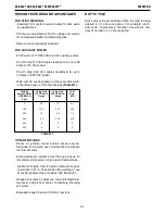
Page 14: ... economy Engine protection system shuts the engine down for low engine oil pressure or high coolant temperature Electronic Engine Idler Engine automatically goes to low idle in 14 to 15 seconds after welding or use of auxiliary power stops Includes high idle switch Gauges for engine oil pressure coolant temperature fuel level engine hour meter and battery charging volt meter Extended range 29 gall...

Page 15: ...ed for 2 seconds followed by the engine hours for 6 seconds The engine hour meter records the total running time on the engine in hours It can be used to keep a record of maintenance on the engine and or welder FUEL LEVEL Displays the fuel level in the fuel tank BATTERY CHARGE VOLT METER Displays the voltage going from the charging alternator into the battery It is normal for charging voltage to b...

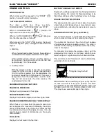
Page 16: ... current with the Job Selector moves the setting outside the black range causing undesirable arc characteristics turn the Job Selector back to the center of the black range Then turn the Current Control up or down a little as needed Readjust the Job Selector for the exact characteristics and current desired REMOTE CONTROL A receptacle and Local Remote control switch on the lower front control pane...

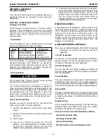
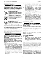
Page 17: ...f the engine fails to start in 60 seconds wait 30 seconds and repeat the above procedure Do not allow the starter motor to run continuously for more then 20 seconds 4 Observe the oil pressure If no pressure shows within 20 seconds stop the engine and consult the engine operating manual To stop the engine turn the IDLER switch to STOP 5 If the engine protection warning light comes on during crankin...

Page 18: ...f the SAE 500 for vari ous operating scenarios is shown below Low Idle No Load 0 34 gal hr 1180 RPM 1 30 L hr High Idle No Load 0 83 gal hr 1800 RPM 3 13 L hr Welding Load 2 07 gal hr 400 Amps 40 Volts 7 85 L hr Welding Load 2 50 gal hr 500 Amps 40 Volts 9 46 L hr Auxiliary Power 0 87 gal hr 3000VA 3 30 L hr ...

Page 19: ... 1 Trailer A 2 wheel trailer designed for road 1 off road in plant and yard towing Trailer mounts directly to welder base Comes standard with a Duo Hitch a 2 Ball and Lunette Eye combination Hitch Order K2637 1 Trailer K2639 1 Fender Light Kit K2640 1 Cable Storage Rack 1For highway use consult applicable federal state and local laws regarding possible requirements for brakes lights fenders etc K7...

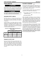
Page 20: ... Change the oil filter in accor dance with the instructions in the engine operating man ual When the oil filter is changed add one quart of oil to the crankcase to replace the oil held in the filter during operation 4 Belts tend to loosen after the first 30 or 40 hours of oper ation Check the cooling fan belt and tighten if neces sary DO NOT OVER TIGHTEN ENGINE OIL CHANGE The SAE 500 SEVERE DUTY i...

Page 21: ...e air To seat the slip ring brushes position the brushes in place Then slide one end of a piece of fine sandpaper between slip rings and brushes with the coarse side against the brushes Pull the sandpaper around the cir cumference of the rings in direction of rotation only until brushes seat properly In addition stone slip ring with a fine stone Brushes must be seated 100 Arcing or excessive excit...

Page 22: ...ct a qualified certified electrician who can assess the situation rewire the GFCI if necessary or replace the device GFCI RECEPTACLE TESTING AND RESETTING PROCEDURE The GFCI receptacle should be properly tested at least once every month or whenever it is tripped To properly test and reset the GFCI receptacle If the receptacle has tripped first carefully remove any load and check it for damage If t...

Page 23: ...ly adjust itself and distribute the sealing pressure evenly To complete a tight seal apply pressure by hand at the outer rim of the filter not the flexible center Avoid pushing on the center of the urethane end cap No cover pressure is required to hold the seal NEVER use the service cover to push the filter into place Using the cover to push the filter in could cause damage to the housing cover fa...

Page 24: ...ok under the column labeled PROBLEM SYMP TOMS This column describes possible symptoms that the machine may exhibit Find the listing that best describes the symptom that the machine is exhibiting Step 2 POSSIBLE CAUSE The second column labeled POSSIBLE CAUSE lists the obvious external possibilities that may contribute to the machine symptom Step 3 RECOMMENDED COURSE OF ACTION This column provides a...

Page 25: ...rature or low oil pres sure engine protection light lit 7 Air intake shut off is closed Manually reset inside machine 8 Low battery voltage 1 Rough or dirty commutator 2 Brushes may be worn down to limit of life 3 Brush springs may be broken 4 Field circuit may have variable resistance connections or inter mittent open circuit due to loose connections or broken wire 5 Electrode or work lead connec...

Page 26: ... low 2 Loose battery cable connections which may need Inspected cleaned or tighten 3 Faulty wiring in engine starting cir cuit 4 Faulty engine starter Contact autho rized local Engine Service Shop 5 If check engine light is on contact your Field Service Facility 6 Check 30A Breaker ECU 1 Low oil pressure engine protection light lit Check oil level Consult engine service dealer 2 High oil temperatu...

Page 27: ...tion 5 Exciter may have lost excitation 1 Series field circuit may be open circuited 2 Current setting may be too high 3 Polarity may be wrong 1 Current Control shaft and han dle may have turned slightly in the insulated bushing of the cur rent control brushholder caused by turning handle too hard against one of the stops 2 Exciter output low causing low output compared to dial indica tion 3 Curre...

Page 28: ...xiliary power 1 Faulty battery 2 Faulty engine alternator 3 Loose or broken lead in charging circuit 4 Loose fan belt may need tightening 1 Idler switch in HIGH idle position make sure switch is set to AUTO 2 Faulty relay 1 Poor work lead connection to work 2 Welding Terminals switch in wrong position CV Mode 3 No open circuit voltage at output studs 1 Broken wire in auxiliary current sensor wirin...

Page 29: ...el too low 157 Sensor error rail pressure signal range check either high or low 168 Sensor error battery voltage signal range check either high or low Warning threshold exceeded either high or low battery voltage 190 Engine speed above warning threshold FOC Level 1 or FOC Level 2 Offset angle between crank and camshaft sensor is too large Speed detection out of range signal disrupted or no signal ...

Page 30: ...from supervisory monitoring function 523776 Timeout Error of CAN Receive Frame TSC1TE active 523777 Passive Timeout Error of CAN Receive Frame TSC1TE Setpoint 523895 Check of missing injector adjustment value programming IMA injector 1 in firing order 523896 check of missing injector adjustment value programming IMA injector 2 in firing order 523897 check of missing injector adjustment value progr...

Page 31: ...5A ECA45A 405A ECB90A ECB26A ECB53 ECB75 ECB53A ECB75A H G B A 5W 236E 236C 30A ECB70 ECB15 70A 20A 226A 236B 236C 236E 236 R3 ECB53B ECB75B 202 ECB54 ECB76 ECB54A ECB76A START 232N COOLANT LEVEL WATER IN FUEL CB5 85 86 87 30 87A CB6 CB8 R5 R2 232K ECB57 ECB64 ECB13 ECB87 ECB29 73 28 2 3 ECB73 ECB28 20A CB7 236A DIAGNOSTIC PLUG 62 PIN ENGINE CONNECTOR 60 PIN ECU A CONNECTOR 94 PIN ECU B CONNECTOR ...

Page 32: ...6A ECA35A ECA45A 405A ECB90A ECB26A ECB53 ECB75 ECB53A ECB75A H G B A 5W 236E 236C 30A ECB70 ECB15 70A 20A 226A 236B 236C 236E 236 R3 ECB53B ECB75B 202 ECB54 ECB76 ECB54A ECB76A START 232N COOLANT LEVEL WATER IN FUEL CB5 85 86 87 30 87A CB6 CB8 R5 R2 232K ECB57 ECB64 ECB13 ECB87 ECB29 73 28 2 3 ECB73 ECB28 20A CB7 236A DIAGNOSTIC PLUG 62 PIN ENGINE CONNECTOR 60 PIN ECU A CONNECTOR 94 PIN ECU B CON...

Page 33: ... 01 27 27 22 50 38 63 63 37 45 83 6 00 24 50 28 14 83 01 44 67 26 33 49 77 CENTER OF GRAVITY WITH OIL IN ENGINE BUT NO FUEL 77 02 N A 20 00 N B 2 13 73 88 14 03 44 50 N B N A N A 0 3 2 DIA MOUNTING HOLES FOR TRAILER N B 0 8 1 DIA MOUNTING HOLES FOR TRAILER 15 32 ...

Page 34: ...parts or electrode with skin or wet clothing l Insulate yourself from work and ground l No toque las partes o los electrodos bajo carga con la piel o ropa moja da l Aislese del trabajo y de la tierra l Ne laissez ni la peau ni des vête ments mouillés entrer en contact avec des pièces sous tension l Isolez vous du travail et de la terre l Berühren Sie keine stromführenden Teile oder Elektroden mit ...

Page 35: ... und Entlüftung des Arbeitsplatzes l Mantenha seu rosto da fumaça l Use ventilação e exhaustão para remover fumo da zona respiratória l Turn power off before servicing l Desconectar el cable de ali mentación de poder de la máquina antes de iniciar cualquier servicio l Débranchez le courant avant l entre tien l Strom vor Wartungsarbeiten abschalten Netzstrom völlig öff nen Maschine anhalten l Não o...

Page 36: ...stomer s particular purpose with respect to such information or advice As a matter of practical consideration we also cannot assume any responsibility for updating or correcting any such information or advice once it has been given nor does the provision of information or advice create expand or alter any warranty with respect to the sale of our products Lincoln Electric is a responsive manufactur...

Reviews: