


Available Equipment:
K1655-1 LFA 3.1, 10 ft. Extraction Arm
K1655-2 LFA 4.1, 13 ft. Extraction Arm
K1655-3 LTA 2.0, Telescopic Extraction Arm
K1534-2 Air Exhaust Silencer
K1654-1 Statiflex 200-M, Wall-mounted Filter Unit
K1494-2 Starter/Overload Switch
(unnecessary if using a K1669-2 Lamp Kit)
K1669-2 Lamp Kit for Wall-Mounted Systems
(replaces K1494-2 Starter/OL Switch)
K1670-1 Automatic Start/Stop Arc Sensor
(requires K1669-2 Lamp Kit)
K1671-1 Extension Crane, 7 ft.
K1671-2 Extension Crane, 14 ft.
K1672-1 Feeder Hanging Rail for Extension Crane
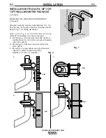
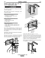
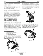
INSTALLING WITh AN LFA 10FT. OR
13FT. WALL-MOUNTED PACKAGE
The installer is responsible for following local safety
codes and regulations.
------------------------------------------------------------------------
Before drilling, verify locations of existing gas, water,
or electrical conduits.
------------------------------------------------------------------------
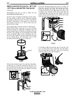
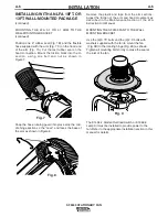
K1655-1 LFA 3.1 or K1655-2 LFA 4.1 Arm Includes:
• Assembled arm, 2 sections
• Flexible hose, (2) 8” Rubber seals for hood hinge
• Hood assembly
• (2) Bolts, M8x1.25, 45mm long (about 1.75”)
• (2) Nuts, M8 self-locking
• Hose running guard
• Clamping pin for red plastic ring
• Metal rotating hinge
• Red plastic ring
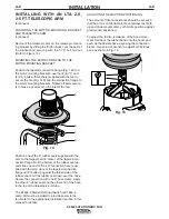
K1657-1 Wall Mounting Bracket Includes:
• (2) Bracket pieces
• Hanging Adapter
• Spring Bracket
• Flexible Hose, (2) 8” Rubber bands for arm base
• (2) Bolts, M8x1.25, 45mm long (about 1.75”)
• (4) Bolts, M8x1.25, 75mm long (about 3.00”)
• (6) Nuts, M8 self-locking
• (6) Washers, M8
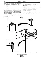
K1656-1 SF2400 Stationary Fan Includes:
• SF2400 Stationary Fan
• (2) Bolts, M8x1.25, 20mm long (about 0.75”)
• (2) Bolts, M8x1.25, 65mm long (about 2.50”)
• (4) Washers, M8
Note: K1494-2 Starter/Overload or K1669-2 Lamp Kit
must be installed with this package. See the installa-
tion section later in this manual for details on installing
this equipment.
A-3
INSTALLATION
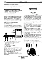
SF2400 STATIONARY FAN
A-3
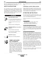
Read this entire installation section before you
start installation.
SAFETY PRECAUTIONS
Do not attempt to use this equipment until you have
thoroughly read all installation, operating and mainte-
nance information supplied with your equipment. They
include important safety precautions and detailed
operating and maintenance instructions.
ELECTRIC ShOCK can kill.
• Do not touch electrically live parts such
as internal wiring.
• Turn the input power off at the fuse box
before working on this equipment.
• Have a qualified person install and ser-
vice this equipment.
------------------------------------------------------------------------
MOVING PARTS can injure.
• Do not operate with covers open or fil-
ter removed.
• Keep away from moving parts.
------------------------------------------------------------------------
Only qualified personnel should install, use or service
this equipment.
GENERAL DESCRIPTION
The K1656-1 SF2400 Stationary Fan provides a low
vacuum, high volume airflow for fume extraction and
ventilation applications. It is intended for use with
large diameter (6-8 in.) flexible arms or hoods.
The SF2400 fan is most commonly used with the LFA
3.1/4.1, 10 ft. and 13 ft. spring-balanced, articulated
arms or LTA 2.0, 3-5 ft. Telescopic Arm (for small
booth or workstation applications). Extracted air can
be vented outside through an Air Exhaust Silencer, or
filtered through a Statiflex 200-M Wall-Mounted Filter
Unit. The Starter/Overload Switch for the SF2400
Extraction Fan protects the motor against overcurrent.
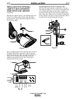
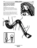
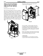
The optional Lamp Kit for Wall-Mounted Systems pro-
vides a work lamp, remote hood-mounted switches for
the lamp and extraction fan, and overload protection,
(thus replacing the starter/overload switch). The
Automatic Start/Stop Arc Sensor can be installed with
the Lamp Kit to turn the extraction fan on and off auto-
matically when an arc flash is detected. Extension
Cranes in 7ft. and 14 ft. lengths, and a Feeder
Hanging Rail for use with extension cranes further
expand system possibilities.
WARNING
WARNING
Summary of Contents for SF2400 STATIONARY FAN IM622
Page 27: ...NOTES SF2400 STATIONARY FAN ...


