background image

ii

SAFETY

ii

ARC RAYS can burn.

4.a. Use  a  shield  with  the  proper  filter  and  cover

plates  to  protect  your  eyes  from  sparks  and
the rays of the arc when welding or observing
open  arc  welding.  Headshield  and  filter  lens
should conform to ANSI Z87. I standards.

4.b. Use  suitable  clothing  made  from  durable  flame-resistant

material  to  protect  your  skin  and  that  of  your  helpers  from
the arc rays.

4.c. Protect other nearby personnel with suitable, non-flammable

screening and/or warn them not to watch the arc nor expose
themselves to the arc rays or to hot spatter or metal.

ELECTRIC  SHOCK  can
kill.

3.a. The  electrode  and  work  (or  ground)  circuits

are  electrically  “hot”  when  the  welder  is  on.
Do not touch these “hot” parts with your bare
skin  or  wet  clothing.  Wear  dry,  hole-free

gloves to insulate hands.

3.b. Insulate yourself from work and ground using dry insulation.

Make certain the insulation is large enough to cover your full
area of physical contact with work and ground.

In  addition  to  the  normal  safety  precautions,  if  welding
must  be  performed  under  electrically  hazardous
conditions  (in  damp  locations  or  while  wearing  wet
clothing; on metal structures such as floors, gratings or
scaffolds;  when  in  cramped  positions  such  as  sitting,
kneeling or lying, if there is a high risk of unavoidable or
accidental  contact  with  the  workpiece  or  ground)  use
the following equipment:

• Semiautomatic DC Constant Voltage (Wire) Welder.
• DC Manual (Stick) Welder.
• AC Welder with Reduced Voltage Control.

3.c. In  semiautomatic  or  automatic  wire  welding,  the  electrode,

electrode  reel,  welding  head,  nozzle  or  semiautomatic
welding gun are also electrically “hot”.

3.d. Always  be  sure  the  work  cable  makes  a  good  electrical

connection  with  the  metal  being  welded.  The  connection
should be as close as possible to the area being welded.

3.e. Ground the work or metal to be welded to a good electrical

(earth) ground.

3.f. Maintain the electrode holder, work clamp, welding cable and

welding machine in good, safe operating condition. Replace
damaged insulation.

3.g. Never dip the electrode in water for cooling.

3.h. Never  simultaneously  touch  electrically  “hot”  parts  of

electrode holders connected to two welders because voltage
between the two can be the total of the open circuit voltage
of both welders.

3.i. When working above floor level, use a safety belt to protect

yourself from a fall should you get a shock.

3.j. Also see Items 6.c. and 8.

FUMES AND GASES
can be dangerous.

5.a. Welding  may  produce  fumes  and  gases

hazardous to health. Avoid breathing these
fumes  and  gases.  When  welding,  keep
your  head  out  of  the  fume.  Use  enough
ventilation and/or exhaust at the arc to keep

fumes  and  gases  away  from  the  breathing  zone. 

When

welding  with  electrodes  which  require  special
ventilation  such  as  stainless  or  hard  facing  (see
instructions  on  container  or  MSDS)  or  on  lead  or
cadmium  plated  steel  and  other  metals  or  coatings
which  produce  highly  toxic  fumes,  keep  exposure  as
low  as  possible  and  within  applicable  OSHA  PEL  and   

ACGIH  TLV  limits  using  local  exhaust  or  mechanical
ventilation.  In  confined  spaces  or  in  some  circum-
stances,  outdoors,  a  respirator  may  be  required.
Additional  precautions  are  also  required  when  welding
on galvanized  steel.

5. b.  The operation of welding fume control equipment is affected

by  various  factors  including  proper  use  and  positioning  of
the equipment, maintenance of the equipment and the spe-
cific  welding  procedure  and  application  involved.    Worker
exposure  level  should  be  checked  upon  installation  and
periodically  thereafter  to  be  certain  it  is  within  applicable
OSHA PEL and ACGIH TLV limits.

5.c. Do not weld in locations near chlorinated hydrocarbon vapors

coming  from  degreasing,  cleaning  or  spraying  operations.
The heat and rays of the arc can react with solvent vapors to
form phosgene, a highly toxic gas, and other irritating prod-
ucts.

5.d. Shielding  gases  used  for  arc  welding  can  displace  air  and

cause  injury  or  death.  Always  use  enough  ventilation,
especially  in  confined  areas,  to  insure  breathing  air  is  safe.

5.e. Read and understand the manufacturer’s instructions for this

equipment  and  the  consumables  to  be  used,  including  the
material  safety  data  sheet  (MSDS)  and  follow  your
employer’s safety practices. MSDS forms are available from
your  welding  distributor  or  from  the  manufacturer.

5.f. Also see item 1.b.

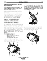
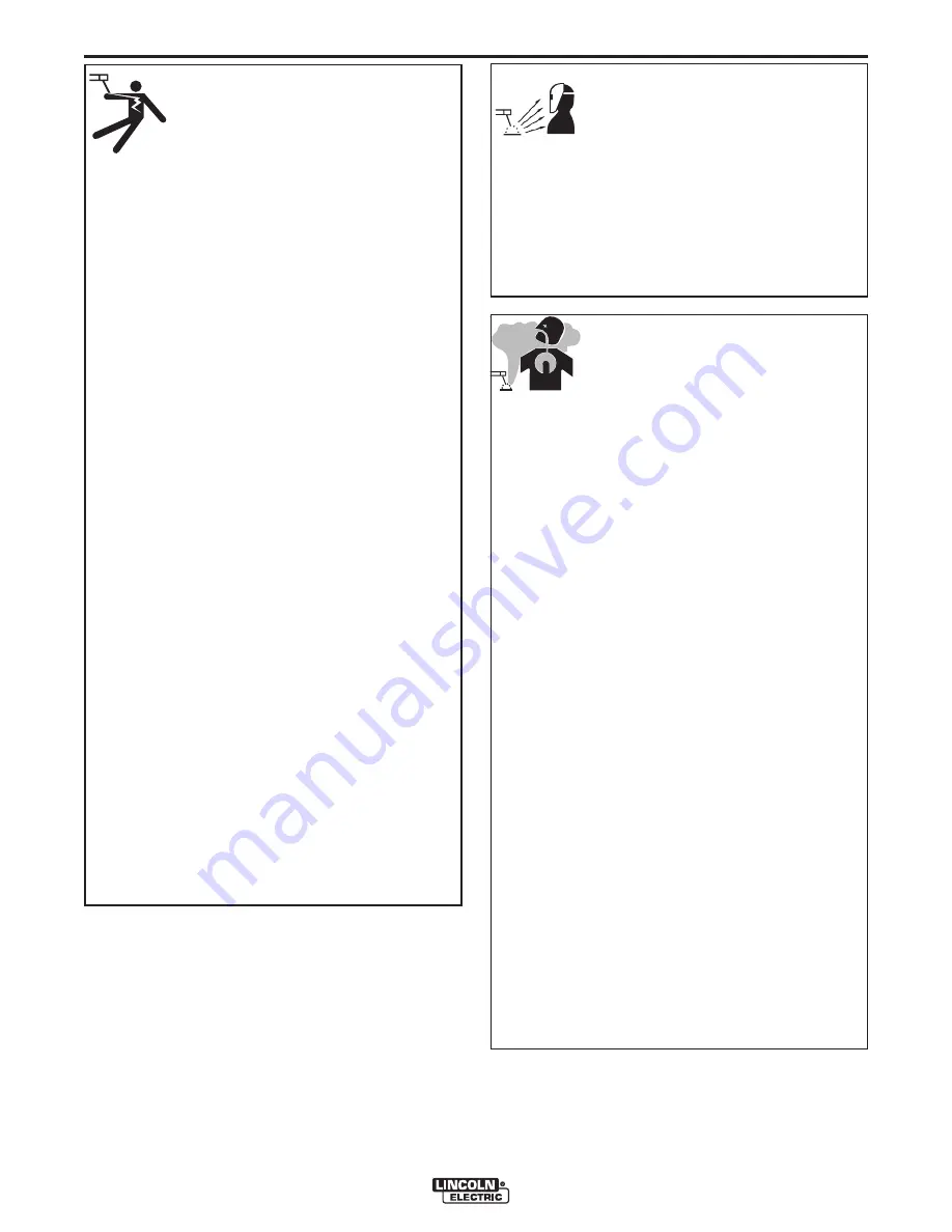
Summary of Contents for SF2400 STATIONARY FAN IM622

Page 1: ... DO NOT I NSTALL OPERATE OR REPAI R THI S EQUI PM ENT W I THOUT READ I NG THI S M ANUAL AND THE SAFETY PRECAUTI ONS CON TAI NED THROUGHOUT And most importantly think before you act and be careful April 2010 IM622 Sales and Service through Subsidiaries and Distributors Worldwide Cleveland Ohio 44117 1199 U S A TEL 216 481 8100 FAX 216 486 1751 WEB SITE www lincolnelectric com World s Leader in Weld...

Page 2: ...AKER WEARERS ShOULD CONSULT WITh ThEIR DOCTOR bEFORE OPERATING Read and understand the following safety highlights For additional safety information it is strongly recommended that you purchase a copy of Safety in Welding Cutting ANSI Standard Z49 1 from the American Welding Society P O Box 351040 Miami Florida 33135 or CSA Standard W117 2 1974 A Free copy of Arc Welding Safety booklet E205 is ava...

Page 3: ...or cooling 3 h Never simultaneously touch electrically hot parts of electrode holders connected to two welders because voltage between the two can be the total of the open circuit voltage of both welders 3 i When working above floor level use a safety belt to protect yourself from a fall should you get a shock 3 j Also see Items 6 c and 8 FUMES AND GASES can be dangerous 5 a Welding may produce fu...

Page 4: ...s to adjacent areas Avoid welding near hydraulic lines Have a fire extinguisher readily available 6 b Where compressed gases are to be used at the job site special precautions should be used to prevent hazardous situations Refer to Safety in Welding and Cutting ANSI Standard Z49 1 and the operating information for the equipment being used 6 c When not welding make certain no part of the electrode ...

Page 5: ...riés et non inflamma bles 4 Des gouttes de laitier en fusion sont émises de l arc de soudage Se protéger avec des vêtements de protection libres de l huile tels que les gants en cuir chemise épaisse pantalons sans revers et chaussures montantes 5 Toujours porter des lunettes de sécurité dans la zone de soudage Utiliser des lunettes avec écrans lateraux dans les zones où l on pique le laitier 6 Elo...

Page 6: ...damage to this equipment CAUTION Please Examine Carton and Equipment For Damage Immediately When this equipment is shipped title passes to the purchaser upon receipt by the carrier Consequently Claims for material damaged in shipment must be made by the purchaser against the transportation company at the time the shipment is received Please record your equipment identification information below fo...

Page 7: ... optional Statiflex 200 M A 10 Installing the Starter Overload Switch A 11 Installing the optional Lamp Kit and Automatic Start Stop Arc Sensor A 11 Operation Section b Safety Instructions B 1 Operating Instructions B 1 Maintenance Section C Routine Maintenance C 1 Trouble Shooting Section D Trouble Shooting Chart D 1 Wiring Diagram Section E Wiring Diagram for SF2400 Fan with K1494 2 Starter Over...

Page 8: ...ithout prior notice Specifications and guarantees are valid only when specified spare parts and filters are used Technical Specifications SF2400 Stationary Fan Sales Spec K1656 1 Input Voltage 115V 1 Ph 60 Hz Rated Current Draw 9 4 A Power Rating 0 75 kW Sound Level 69 dB A Weight 28 lbs 14 kg GENERAL Min Temperature 41 o F 5 o C Max Temperature 113 o F 45 o C Max Rel humidity 80 AMbIENT CONDITION...

Page 9: ...TA 2 0 Vacuum Inches WG Air Flow CFM 6 4 2 0 0 250 500 750 1000 SF 2400 LTA 2 0 Vacuum Inches WG Air Flow CFM Technical Specifications SF2400 Stationary Fan 0 ft 3 ft 6 ft 10 ft 13 ft 0 ft 3 ft 6 ft 10 ft 13 ft 16 ft 20 ft 45 45 40 1000 mm 40 1000 mm 40 1000 mm 55 1400 mm 55 1400 mm PRESSURE DROP SF2400 Fan and LFA 3 1 4 1 Arms Vacuum inches WG vs Airflow CFM PRESSURE DROP SF2400 Fan and LTA 2 0 A...

Page 10: ...his entire installation section before you start installation SAFETY PRECAUTIONS Do not attempt to use this equipment until you have thoroughly read all installation operating and mainte nance information supplied with your equipment They include important safety precautions and detailed operating and maintenance instructions ELECTRIC ShOCK can kill Do not touch electrically live parts such as int...

Page 11: ...ing dimensions Refer to the Fig 2 for recommended mounting methods for installation on various wall types A Mounting on a thin wall recommended minimum wall thickness 5 in 100 mm using four threaded rods 3 8 in M10 B Mounting on a thick wall using four cotter bolts 3 8 in M10 C Mounting on a steel I beam using four threaded rods 3 8 in M10 and two box profile stabilizers 1x1x0 1 in 30x30x3 A C B 3...

Page 12: ...ac tion arm sections until the arm is completely installed including mounting the hood The arm is spring bal anced to compensate for the weight of the hood and will spring out quickly if it is not mounted securely with the hood in place The rotating hinge of the arm comes in three pieces Metal rotating hinge red plastic ring and clamping pin Refer to Figure 3 Mount the red plastic ring to the meta...

Page 13: ...nose end faces the base of the arm as shown in Figure 8 Remove the plastic and tape from the arm sections Adjust the friction of the arm and hood movement as described in the Maintenance Section of the LFA Extraction Arm Manual MOUNTING THE SF2400 FAN TO THE WALL MOUNTING BRACKET Use the 2 0 75 bolts and the 2 2 5 bolts with washers supplied with the fan to mount the fan Fig 9B to the rotating hin...

Page 14: ...the appropri ate Installation section in this manual for details on this equipment MOUNTING THE MOTOR MOUNTING BRACKET AND TELESCOPIC ARM Disconnect the telescopic mounting bracket from the arm before mounting by removing the 1 75 bolt Fig 12C and sliding the post out of the friction block Drill 5 holes Reference Figures 11 12 13 Mount the motor mounting bracket and the telescopic mounting bracket...

Page 15: ...bottom of the rubber seal up and slide one end of the 4 ft connection hose sup plied with the arm up over the tapered connection flange until it butts up against the folded side of the rubber seal Fold the rubber seal down over the hose Secure the connection with one 8 hose clamp Apply the other 8 rubber seal and the other end of the hose to the top of the telescopic arm tube The K1494 2 Starter O...

Page 16: ...for side to side movement of the arm use the top two bolt nut sets on the rotat ing hinge Fig 16A To adjust the friction setting for front to back move ment adjust the front bolt nut set Fig 16E on the rotating hinge To adjust the friction setting for the telescopic motion of the arm remove the black cap Fig 16B and turn the set screw Fig 16D Counterclockwise to increase friction and Clockwise to ...

Page 17: ...er side of the 6 8 Reducer Secure with one 8 hose clamp Mount the Statiflex mounting bracket Fig 17A to the wall where convenient with the following in mind Access to the filter for maintenance is by lifting the large red cover over the internal filter The easiest method is to lift the entire filter unit off the mounting bracket about 2 4 higher than its mounting height and set it down on the floo...

Page 18: ...raction fan on and off when it sens es an arc Installation instructions include directions for mounting both the Lamp Kit and Sensor If not installing the Auto start stop feature skip steps as indicated The K1669 2 Lamp Kit includes Work Lamp WL 36 ft Connection Cable NCW 11 Connection Box CB Thermal Relay 8 12 5A NTR Pop out the sealing plate Fig 19A on the top of the hood with a screwdriver Remo...

Page 19: ... remote switch Fig 23C Snap the switch box Fig 23A into the top of the hood by squeezing the front and back If installing with an LTA 2 0 Telescopic Arm With the arm fully extended route the 36 ft connect ing cable through the arm securing it to the guide arm in two places with cable ties as shown in Figure 24 Exit the arm through the hole near the rotating hinge Fig 24A use a knife to cut an X pa...

Page 20: ...our cable holders in the arm Fig 26D Leave plenty of slack at each hinge Fig 26A 22 in at the middle hinge Secure the cable in the cable holders Fig 26 Inset and use wire ties at the hinge as shown in Fig 25 Exit the arm through the cable hole in the rotating hinge use a knife to cut a small X pattern in the grom met as shown in Figure 24 4x D D A B A C A D D Fig 26 L min 22 550 mm C L min 22 550 ...

Page 21: ... control box when referencing Figures 27 28 and the wiring dia gram Mount the connection box to the wall using four screws as shown in Figure 28 Feed a 120VAC 1ph 60Hz supply cable into the Control Box Route a power cable out of the box to the terminal box on the motor of the SF2400 fan Route the 36 ft connection cable into the Control Box Connect all cables per the wiring diagram in the back of t...

Page 22: ...sure proper vacuum operation and cooling air flow OPERATING INSTRUCTIONS Use the wall mounted starter overload switch or the hood mounted remote switch if a lamp kit is installed to turn on the SF2400 Stationary Fan Position hood within 10 15 inches 250 400 mm of the arc If using a Lamp Kit The switch on the hood with a lamp symbol operates the work lamp in the hood The 0 1 switch operates the SF2...

Page 23: ...housing for encrusted particles and clean if necessary Check the sealing material of the extraction fan and replace if necessary If used refer to the Statiflex 200 M Extraction arm Extension crane Lamp kit and Auto start stop arc sensor manuals for required routine maintenance operations SF2400 STATIONARY FAN ...

Page 24: ...e or not connected Motor overload protection activated Motor defective or damaged Leakage Outlet grid blocked Air path in arm blocked Filter blocked check Maintenance Indicator Spark arrester blocked Blower fan blocked Fan seal damaged Filter damaged or not seated cor rectly Imbalance in the fan Verify 120VAC 60Hz 1ph input power Check the integrity of the input cord Check the contacts Repair or r...

Page 25: ...PUT POWER 115V 1PH 60HZ L N GND L N L N GND GND L L N N STARTER OVERLOAD SWITCH GND GND 1 L1 3 L2 5 L3 2 T1 4 T2 6 T3 L L 10 13 16 STOP START See motor terminal cover for wiring instructions that pertain to the specific motor type FAN MOTOR INPUT POWER 115V 1PH 60HZ L N GND L N L N GND GND L L N N STARTER OVERLOAD SWITCH GND GND WIRING DIAGRAM FOR SF2400 FAN WITh K1494 2 STARTER OVERLOAD SWITCh ...

Page 26: ...NTROL BOX See motor terminal cover for wiring instructions that pertain to the specific motor type FAN MOTOR GN BN WH WH BN GN WH BN GN BK BK LAMP I O WORK LAMP L N GND GND WH BN GN AUTO START STOP ARC SENSOR REMOTE SWITCH LAMP 36 FT CABLE INPUT POWER 115V 1PH 60HZ L N GND TR 188 83 SERIE 9740 0 115V 230V 400V Primair SEC 24V 48VA BL BN BN WH BN FUSE 1L1 3L2 5L3 1 1 3 3 4 4 21 22 2T1 4T2 6T3 A2 A1...

Page 27: ...NOTES SF2400 STATIONARY FAN ...

Page 28: ... N E IN SAT Z D E S H E RST E LLE RS D IE UN FA LLV E RH Ü T UN G SVO RSC H RIF T E N D E S A RBE IT G E l D o not touch electricallylivepartsor electrodewith skin or wet clothing l Insulateyourself from work and ground l N o toquelasparteso loselectrodos bajo cargacon lapiel o ropamojada l A islesedel trabajo y delatierra l N elaissez ni lapeau ni desvêtements mouillésentrer en contact avecdes pi...

Page 29: ...eibrauch l Sorgen Siefür guteBe und E ntlüftung desA rbeitsplatzes l M antenhaseu rosto dafumaça l Useventilação eexhaustão para remover fumo dazonarespiratória l T urn power off beforeservicing l D esconectar el cabledealimentación depoder delamáquinaantesdeini ciar cualquier servicio l D ébranchez lecourant avant l entre tien l Strom vor W artungsarbeiten abschalten N etzstrom völlig öff nen M a...

Page 30: ...s and Service through Subsidiaries and Distributors Worldwide Cleveland Ohio 44117 1199 U S A TEL 216 481 8100 FAX 216 486 1751 WEB SITE www lincolnelectric com World s Leader in Welding and Cutting Products ...

Reviews: