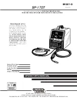
background image

SP-170T

OPERATOR’S MANUAL

IM537-D

March, 2001

Safety Depends on You

Lincoln arc welding and cutting
equipment is designed and built
with safety in mind. However,
your overall safety can be
increased by proper installation ...
and thoughtful operation on your
part.

DO NOT INSTALL, OPER-

ATE OR REPAIR THIS EQUIP-
MENT WITHOUT READING
THIS MANUAL AND THE SAFE-
TY PRECAUTIONS CONTAINED
THROUGHOUT.

And, most

importantly, think before you act
and be careful.

For use with machine Code Numbers

10023 thru 10026,10134,10162,

10163,10261,10264,10272,10482,10691,10692,10741,10842 and 10848

• Sales and Service through Subsidiaries and Distributors Worldwide •

Cleveland, Ohio 44117-1199 U.S.A. TEL: 216.481.8100 FAX: 216.486.1751 WEB SITE: www.lincolnelectric.com

• World's Leader in Welding and Cutting Products •

Date of Purchase:
Serial Number:
Code Number:
Model:
Where Purchased:

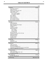
Summary of Contents for SP-170T

Page 1: ...G THIS MANUAL AND THE SAFE TY PRECAUTIONS CONTAINED THROUGHOUT And most importantly think before you act and be careful For use with machine Code Numbers 10023 thru 10026 10134 10162 10163 10261 10264 10272 10482 10691 10692 10741 10842 and 10848 Sales and Service through Subsidiaries and Distributors Worldwide Cleveland Ohio 44117 1199 U S A TEL 216 481 8100 FAX 216 486 1751 WEB SITE www lincolne...

Page 2: ...MAKER WEARERS SHOULD CONSULT WITH THEIR DOCTOR BEFORE OPERATING Read and understand the following safety highlights For additional safety information it is strongly recommended that you purchase a copy of Safety in Welding Cutting ANSI Standard Z49 1 from the American Welding Society P O Box 351040 Miami Florida 33135 or CSA Standard W117 2 1974 A Free copy of Arc Welding Safety booklet E205 is av...

Page 3: ...ectrical earth ground 3 f Maintain the electrode holder work clamp welding cable and welding machine in good safe operating condition Replace damaged insulation 3 g Never dip the electrode in water for cooling 3 h Never simultaneously touch electrically hot parts of electrode holders connected to two welders because voltage between the two can be the total of the open circuit voltage of both welde...

Page 4: ...o prevent the welding sparks from starting a fire Remember that welding sparks and hot materials from welding can easily go through small cracks and openings to adjacent areas Avoid welding near hydraulic lines Have a fire extinguisher readily available 6 b Where compressed gases are to be used at the job site special precautions should be used to prevent hazardous situations Refer to Safety in We...

Page 5: ... non inflammables 4 Des gouttes de laitier en fusion sont émises de l arc de soudage Se protéger avec des vêtements de protection libres de l huile tels que les gants en cuir chemise épaisse pan talons sans revers et chaussures montantes 5 Toujours porter des lunettes de sécurité dans la zone de soudage Utiliser des lunettes avec écrans lateraux dans les zones où l on pique le laitier 6 Eloigner l...

Page 6: ...re the information must be followed to avoid minor personal injury or damage to this equipment CAUTION Please Examine Carton and Equipment For Damage Immediately When this equipment is shipped title passes to the purchaser upon receipt by the carrier Consequently Claims for material damaged in shipment must be made by the purchaser against the transportation company at the time the shipment is rec...

Page 7: ...s B 2 Controls and Settings B 2 Welding Operations B 3 Wire Loading B 3 Wire Threading B 4 Making a Weld B 5 Process Guidelines B 5 Chaning Over to Feed Other Wire Sizes B 6 Welding with GMAW B 6 Welding with FCAW B 6 Overload Protection B 6 Learning to Weld B 7 Application Chart B 18 Accessories Section C Accessories C 1 Replacement Parts C 2 Maintenance Section D Safety Precautions D 1 Routine M...

Page 8: ...COMMENDED INPUT CABLE AND FUSE SIZES Height Width Depth Weight 12 0 in 9 75 in 16 5 in 57 Ibs 305 mm 248 mm 419 mm 25 9 kg PHYSICAL DIMENSIONS Standard Voltage Frequency Input Current 230V 60Hz 20 Amps Rated Output 208V 60Hz 22 Amps Rated Output Duty Cycle Amps Volts at Rated Amperes 20 Duty Cycle 230V 60Hz 130 20 20 Duty Cycle 208V 60Hz 130 20 Welding Current Range Maximum Open Circuit Voltage Wi...

Page 9: ...ve roll 4 10 ft 3 0 m work cable 5 Work clamp 6 Sample Spool of L 56 025 MIG Wire 7 Adjustable mixed Gas Regulator Hose 1 The gun is ready to feed 023 025 diameter wire ELECTRIC SHOCK can kill Only qualified personnel should perform this installation Only personnel that have read and under stood the SP 170T Operating Manual should install and operate this equipment Machine must be plugged into a r...

Page 10: ...hine may topple over if this procedure is not fol lowed OUTPUT CONNECTIONS Refer to Figure A 2 1 Work Cable Access Hole 2 Gun Cable and Control Lead Access Hole 3 Connector Block 4 Gun Trigger Lead Connectors 5 Positive and negative output terminals 6 Wire Feed Gearbox 7 Cable Hanger 8 Thumbscrew Refer to the Accessories Section for available optional equipment Work Clamp Installation Attach the w...

Page 11: ...ble and Control Lead Access Slot 2 in the case front The leads are to be routed up the inside of the case front behind the gas line 3 Insert the connector on the gun conductor cable through the Gun Cable Access Hole 2 in the SP 170T case front Make sure the connector is all the way in the brass connector block to obtain proper gas flow If the gun connector will not fully insert unscrew the thumbsc...

Page 12: ... a wrench Connect the other end to the SP 170T Gas Solenoid Inlet Fitting 5 8 18 female threads for CGA 032 fitting Make certain the gas hose is not kinked or twisted 5 Reinstall case side before connecting input power INPUT CONNECTIONS FIGURE A 6 Refer to Figure A 6 CYLINDER may explode if dam aged Keep cylinder upright and chained to support Keep cylinder away from areas where it may be damaged ...

Page 13: ...nd connect H3 to CR1 4 Insulate unused H1 lead for 300V with electrical tape and secure to lead sleeving 5 Reinstall case side before connecting input power Line Cord Connection A 3 conductor line cord with a 50 amp 250 volt three prong plug NEMA Type 6 50P is factory installed Connect this plug to a mating grounded receptacle which is connected to an appropriate power supply per the U S National ...

Page 14: ...s having access to 230 or 208 volt 60 Hz AC input power and want the ease of use quality and dependability of both gas metal arc welding or GMAW also known as MIG welding and the Innershield process self shielded flux cored or FCAW A convenient chart is mounted inside the wire feed section door for setting welding procedures for 24 gauge 60 mm through 5 16 8 0 mm mild steel The machine is rugged a...

Page 15: ... 1 2 10 2 m min The control can be preset on the dial to the setting specified on the SP 170T Application Chart located on the inside of the OFF ON ARC VOLTS WIRE SPEED 4 Circuit Breaker Protects machine from damage if maximum output is exceeded Button will extend out when tripped Manual reset See Figure B 1b 5 Gun Trigger Activates welding output wire feed and gas solenoid operation Releasing the...

Page 16: ...Load an 8 200 mm diameter spool on the wire spool spindle shown in Figure B 2 To use 4 100 mm diameter spools the 2 50 mm diameter spindle must be removed See Figure B 3 Remove the wing nut and spacer at the end of the shaft and remove the outside plastic wire spool spin dle The spindle can be stored in the wire feed com partment A 4 100 mm diameter spool is mounted directly on the 5 8 16 mm diame...

Page 17: ...ired to take up extra slack in the wire 6 The idle roll pressure adjustment wing nut is nor mally set for mid position on the pressure arm threads If feeding problems occur because the wire is flattened excessively turn the pressure adjustment counter clockwise to reduce distortion of the wire Slightly less pressure may be required when using 0 023 0 025 0 6 mm wire If the 6 drive roll slips while...

Page 18: ...release the gun trigger and then pull the gun away from the work after the arc goes out FIGURE B 6 10 When no more welding is to be done close valve on gas cylinder if used momentarily operate gun trigger to release gas pressure and turn off the SP 170T Cleaning Tip And Nozzle Clean the contact tip and nozzle to avoid arc bridging between the nozzle and contact tip which can result in a shorted no...

Page 19: ...welding out of position or in a drafty location 3 Keep the cylinder valve closed except when using the SP 170T When finished welding a Close the cylinder valve to stop gas flow b Depress the gun trigger briefly to release the pressure in the gas hose c Turn off the SP 170T WELDING WITH FCAW Innershield When using the FCAW process the correct drive roll and electrode polarity must be used See Work ...

Page 20: ... detailed informa tion order a copy of New Lessons in Arc Welding listed at the end of this manual THE ARC WELDING CIRCUIT The operator s knowledge of arc welding must go beyond the arc itself The operator must know how to control the arc and this requires a knowledge of the welding circuit and the equipment that provides the electric current used in the arc Figure B 7 illustrates the welding circ...

Page 21: ...f the weld during cooling After running a weld bead the slag may be removed with a chipping hammer and wire brush This improves appearance and allows for inspection of the finished weld Since machine size and output characteristics limit the size and type of wire electrode which can be used Lincoln 0 035 and 0 045 0 9 and 1 2 mm NR 211 MP Innershield electrode is recommended for Self Shielded Flux...

Page 22: ...u will be able to weld the material In addition aluminum and stainless steel can be welded using the K664 1 Aluminum Welding Kit For further information on identifying various types of steels and other metals and for proper procedures for welding them we again suggest you purchase a copy of New Lessons in Arc Welding Regardless of the type of metal being welded in order to get a quality weld it is...

Page 23: ...cal up or vertical down Vertical up is used whenever a larger stronger weld is desired Vertical down is used primarily on sheet metal 5 32 3 9 mm and under for fast low penetrating welds Use of this unit on thicker materials than recom mended may result in poor welds The welds may look good but may just be sitting on top of the plate This is called Cold Casting and will result in weld failure Vert...

Page 24: ...to the settings suggested on the Application Guide for the welding wire and base metal thickness being used The voltage control is marked V and the wire feed speed is marked olo 4 Check that the polarity is correct for the welding wire being used Set the polarity for DC when welding with NR 211 MP Innershield electrode See Work Cable Installation in the INSTALLATION section for instructions on cha...

Page 25: ...ickout ESO is the distance from the end of the contact tip to the end of the wire See Figure B 19 Once the arc has been established maintaining the correct ESO becomes extremely important The ESO should be approximately 3 8 to 1 2 inch 10 to 12 mm long FIGURE B 20 FIGURE B 18 WARNING FIGURE B 19 3 8 1 2 10 12 mm Electrical Stickout ESO Contact Tip Wire Electrode Solidifying ridge Molten puddle The...

Page 26: ...orrect welding speed is to perform the following exercise Refer to Figure B 22 1 Learn to strike an arc by positioning the gun over the joint and touching the wire to the work 2 Position face shield to protect face and eyes 3 Depress gun trigger hold gun so contact tip to work distance is about 3 8 to 1 2 inch 10 to 12 mm and the gun is at proper angle 4 After you strike the arc practice the corre...

Page 27: ...of the four welding will be easy They are as follows 1 The Correct Welding Position Figure B 23 illustrates the correct welding position for right handed people For left handed people it is the opposite When GMAW MIG welding on sheet metal it is important to use the forehand push technique Hold the gun of the gun and cable assembly in your right hand and hold the shield with your left hand Left ha...

Page 28: ...ncolnweld 0 025 L 56 electrode CO2 Voltage Setting V C Wire Feed Speed o o 4 For the SP 170 T use the following B 15 LEARNING TO WELD FIGURE B 24 3 The Correct Electrical Stickout ESO The electrical stickout ESO is the distance from the end of the contact tip to the end of the wire See Figure B 24 Once the arc has been established maintaining the correct ESO becomes extremely important The ESO sho...

Page 29: ...s free from moisture oil rust paint or other contaminants To Eliminate a Ropy Convex Bead in order of importance 1 Increase voltage 2 Decrease stickout 3 Decrease WFS wire feed speed 4 Decrease travel speed 5 Decrease drag angle 6 Check for correct gas if used To Reduce Spatter in order of importance 1 Increase voltage 2 Increase drag angle 3 Decrease stickout 4 Increase WFS wire feed speed 5 Decr...

Page 30: ... kink or pull the gun around sharp corners 2 Keep the gun cable as straight as practical when welding 3 Do not allow dolly wheels or trucks to run over the cables 4 Keep the cable clean 5 Innershield electrode has proper surface lubrica tion Use only clean rust free electrode 6 Replace contact tip when it becomes worn or the end is fused or deformed ...

Page 31: ...B 18 SP 170T B 18 APPLICATION CHART ...

Page 32: ...4 KP665 045C Drive Roll Optional Knurled drive roll for feeding 035 045 0 9 1 2 mm diameter flux cored electrode 5 K695 1 Spot Stitch Timer Kit Includes spot timer to control the spot welding arc time and a stitch timer to control the on off cycle time of the arc to prevent burnthrough on thin gauge metals Also includes spot welding nozzle The Spot Stitch Timer Kit installs inside the wire feed co...

Page 33: ...as nozzle if installed and install gasless nozzle To remove simply unscrew 5 Load wire into machine and thread into gun and cable per Welding Wire Loading section REPLACEMENT PARTS Complete Gun and Cable Assembly L8311 6 K530 4 Contact Tip 025 0 6 mm S19726 1 Contact Tip 030 0 8 mm S19726 2 Contact Tip 035 0 9 mm S19726 3 Contact Tip 045 1 2 mm S19726 4 Contact Tip Tapered 025 0 6 mm S20278 1 Cont...

Page 34: ...rt may clog the air passages causing the welder to run hot Blow dirt out of the welder with low pressure air at regular intervals to eliminate excessive dirt and dust build up on interval parts WIRE FEED COMPARTMENT 1 When necessary vacuum accumulated dirt from gearbox and wire feed section 2 Occasionally inspect the incoming guide tube and clean inside diameter if necessary 3 Motor and gearbox ha...

Page 35: ...gun remove gas nozzle or gasless nozzle and remove diffuser from gun tube Remove both collars from each end of the gun handle and separate the handle halves Loosen the locking nut holding the gun tube in place against the gun end cable connector Unscrew gun tube from cable connector To install gun tube screw the locking nut on the gun tube as far as possible Then screw the gun tube into the cable ...

Page 36: ...ring loaded pressure arm and lift the idle roll arm away from the drive roll 3 Turn the power switch to ON marked I 4 Set the wire speed to minimum and jog the drive unit with the trigger switch until the drive roll set screw is facing up When inching the welding wire the drive rolls gun connector block and gun contact tip are energized relative to work and ground and remain energized for several ...

Page 37: ...r out of the cable 1 1 4 31 8 mm Liner Trim Length Gas Diffuser Gas Nozzle or Gasless Nozzle Set Screw Brass Cable Connector Liner Assembly Liner bushing to be sealed tight against brass cable connector FIGURE D 2 Liner trim length 5 Insert a new untrimmed liner into the connector end of the cable Be sure the liner bushing is stenciled appropriately for the wire size being used 6 Fully seat the li...

Page 38: ...ately 60 degrees counter clockwise until the collar reaches a stop Then pull the collar off the gun handle If the collars are diffi cult to turn position the gun handle against a corner place a screwdriver against the tab on the collar and give the screwdriver a sharp blow to turn the collar past an internal locking rib See Figure D 3 FIGURE D 3 Counter clockwise SP 170T ...

Page 39: ... CAUSE lists the obvious external possibilities that may contribute to the machine symptom Step 3 RECOMMENDED COURSE OF ACTION This column provides a course of action for the Possible Cause generally it states to contact your local Lincoln Authorized Field Service Facility If you do not understand or are unable to perform the Recommended Course of Action safely contact your local Lincoln Authorize...

Page 40: ...s in the ON position 3 Make sure circuit breaker inside wire drive compartment is reset 1 The thermostat may be tripped due to overheating Let machine cool Weld at lower duty cycle 2 Check for obstructions in air flow 3 Check Gun Trigger connections See Installation section 4 Gun trigger may be faulty RECOMMENDED COURSE OF ACTION Contact your local Lincoln Authorized Field Service Facility OUTPUT ...

Page 41: ...OMMENDED COURSE OF ACTION Contact your local Lincoln Authorized Field Service Facility FEEDING PROBLEMS If for any reason you do not understand the test procedures or are unable to perform the tests repairs safely contact your LOCAL AUTHORIZED LINCOLN ELECTRIC FIELD SERVICE FACILITY for assistance before you proceed CAUTION PROBLEMS SYMPTOMS Low or no gas flow when gun trigger is pulled Wire feed ...

Page 42: ...ine See Installation sec tion Electrical Input Connections 2 Check for proper electrode polarity for process 3 Check gun tip for wear or dam age and proper size Replace 4 Check for proper gas and flow rate for process For MIG only 5 Check work cable for loose or faulty connections 6 Check gun for damage or breaks 7 Check for proper drive roll orien tation and alignment 8 Check liner for proper siz...

Page 43: ... E R F O R 2 0 8 V I N P U T D I S C O N N E C T W E L D E R F R O M I N P U T P O W E R R E M O V E C A S E S I D E R E M O V E L E A D M A R K E D H 1 F R O M C R 1 R E M O V E T A P E S E C U R I N G H 3 T O L E A D S L E E V I N G A N D C O N N E C T H 3 T O C R 1 I N S U L A T E U N U S E D H 1 L E A D F O R 3 0 0 V W I T H E L E C T R I C A L T A P E A N D S E C U R E T O L E A D S L E E V I...

Page 44: ...SP 170T NOTES ...

Page 45: ...electrically live parts or electrode with skin or wet clothing Insulate yourself from work and ground No toque las partes o los electrodos bajo carga con la piel o ropa moja da Aislese del trabajo y de la tierra Ne laissez ni la peau ni des vête ments mouillés entrer en contact avec des pièces sous tension Isolez vous du travail et de la terre Berühren Sie keine stromführenden Teile oder Elektrode...

Page 46: ...gute Be und Entlüftung des Arbeitsplatzes Mantenha seu rosto da fumaça Use ventilação e exhaustão para remover fumo da zona respiratória Turn power off before servicing Desconectar el cable de ali mentación de poder de la máquina antes de iniciar cualquier servicio Débranchez le courant avant l entre tien Strom vor Wartungsarbeiten abschalten Netzstrom völlig öff nen Maschine anhalten Não opere co...

Page 47: ...s and Service through Subsidiaries and Distributors Worldwide Cleveland Ohio 44117 1199 U S A TEL 216 481 8100 FAX 216 486 1751 WEB SITE www lincolnelectric com World s Leader in Welding and Cutting Products ...

Reviews: