background image

Retur

n to Section TOC

Retur

n to Section TOC

Retur

n to Section TOC

Retur

n to Section TOC

Retur

n to Master TOC

Retur

n to Master TOC

Retur

n to Master TOC

Retur

n to Master TOC

TROUBLESHOOTING & REPAIR

F-85

F-85

SQUARE WAVE TIG 355

RETEST AFTER REPAIR

(continued)

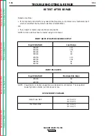
OUTPUT CURRENT RANGE

2 - 400 Amps AC and DC

RECOMMENDED METERS FOR MACHINE OUTPUT TESTS

VOLTMETER:

AC and DC True RMS Meter – Fluke 8922A or equivalent

AMMETER:

Columbia Type AX AC or DC Tong Ammeter

IMPORTANT: IF OTHER TYPE METERS ARE USED RESULTS MAY NOT BE ACCURATE

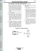
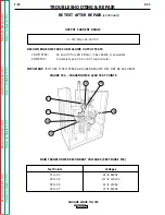
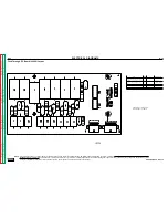
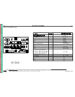
MAIN TRANSFORMER SECONDARY VOLTAGES (SEE FIGURE F32)

Test Points

Voltages

X1 to X2

84 to 89VAC

X3 to X4

117 to 125VAC

X5 to X6

22 to 24VAC

X2 to X7

77 to 81VAC

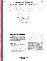
FIGURE F32. – TRANSFORMER LEAD TEST POINTS

X1

X7

X3

X4

X5

X6

X2

Summary of Contents for SQUARE WAVE SVM118-A

Page 1: ...pends on You Lincoln arc welding and cutting equipment is designed and built with safety in mind However your overall safety can be increased by proper installation and thoughtful operation on your part DO NOT INSTALL OPERATE OR REPAIR THIS EQUIPMENT WITHOUT READING THIS MANUAL AND THE SAFETY PRECAUTIONS CONTAINED THROUGHOUT And most importantly think before you act and be careful RETURN TO MAIN I...

Page 2: ...Replace damaged insulation 1 g Never dip the electrode in water for cooling 1 h Never simultaneously touch electrically hot parts of elec trode holders connected to two welders because voltage between the two can be the total of the open circuit voltage of both welders 1 i When working above floor level use a safety belt to protect yourself from a fall should you get a shock 1 j Also see items 4 c...

Page 3: ...a 4 g Connect the work cable to the work as close to the welding area as practical Work cables connected to the building framework or other locations away from the welding area increase the possibility of the welding current passing through lifting chains crane cables or other alternate circuits This can create fire hazards or overheat lifting chains or cables until they fail 4 h Also see item 7c ...

Page 4: ...r the engine fan Do not attempt to override the governor or idler by pushing on the throttle control rods while the engine is running 7 g To prevent accidentally starting gasoline engines while turn ing the engine or welding generator during maintenance work disconnect the spark plug wires distributor cap or magneto wire as appropriate 7 h To avoid scalding do not remove the radiator pressure cap ...

Page 5: ...au soudage à l aide d écrans appropriés et non inflamma bles 4 Des gouttes de laiter en fusion sont émises de l arc de soudage Se protéger avec es vêtements de protection libres de l huile tels que les gants en cuir chemise épaisse pan talons sans revers et chaussures montantes 5 Toujours porter des lunettes de sécurité dans la zone de soudage Utiliser des lunettes avec écrans lateraux dans les zo...

Page 6: ...d Processes B 3 Operational Features and Controls B 3 Design Features and Advantages B 3 Welding Capability B 4 Limitations B 4 Controls and Settings Upper and Lower Case Front Controls B 5 Welding Operation B 15 Overload Protection B 21 Auxiliary Power B 21 Accessories Section C Maintenance Section D Safety Precautions D 2 Input Power Factor Capacitor Discharge Procedure D 2 Routine and Periodic ...

Page 7: ...uare Wave TIG 355 A 2 Input and Output Specifications A 2 Cable and Fuse Sizes A 2 Physical Dimensions A 2 Safety Precautions A 3 Select Suitable Location A 3 Stacking A 3 Lifting A 3 Tilting A 3 High Frequency Precautions A 3 Input Connections A 4 Ground Connection A 4 Input Supply Connections A 4 Reconnect Procedure A 5 Output Connections A 7 TIG Torch Connection A 7 Stick Electrode Cable Connec...

Page 8: ... C Copper Ground Fuse Input Super Lag Ampere Copper Wire in Wire in Conduit Copper Wire in Wire in Conduit Super LAG Voltage or Breaker Rating on Conduit AWG AWG IEC Input Conduit AWG AWG IEC or Breaker Frequency Size Nameplate IEC Sizes Sizes Amperes IEC Sizes Sizes Size 208 60 150 110 4 25mm2 6 16mm2 148 2 35mm2 6 16mm2 200 230 60 125 100 6 16mm2 6 16mm2 134 2 35mm2 6 16mm2 175 460 60 60 50 8 10...

Page 9: ...ctronic equipment interfer ence problems These problems may be the result of radiated interference Proper grounding methods can reduce or eliminate radiated interference The Square Wave TIG 355 has been field tested under recommended installation conditions It complies with FCC allowable limits for radiation For convenience a certificate of compliance is packed with the welder It can be used to pr...

Page 10: ...erference problems and result in unsatisfactory welding per formance resulting from lost high frequency power INPUT CONNECTIONS Be sure the voltage phase and frequency of the input power is as specified on the rating plate located on the front of the machine Welder supply line entry provision is in the case rear panel with a removable cover over the input connec tion panel area See Figure A 1 GROU...

Page 11: ...nals corresponding to the input volt age used Designations on reconnect panel LOW MID and HIGH correspond to the nameplate input voltages of a triple voltage welder Dual voltage welders use only LOW and HIGH Single voltage welders use only HIGH EXAMPLE On a 208 230 460 volt welder LOW is 208V MID is 230V and HIGH is 460V Fuse the input circuit with the recommended super lag fuses or delay type1 ci...

Page 12: ...er Cond AWG Copper Cond Super Lag 208 60 110 4 6 150 230 60 100 6 6 125 460 60 50 8 10 60 200 50 115 4 6 150 220 50 104 4 6 125 440 50 52 8 10 60 TABLE A 2 RECOMMENDED INPUT WIRE AND FUSE SIZES For Unbalanced AC TIG Welding Above 230 AMPS Based on the 1990 U S National Electrical Code 2 60 Duty Cycle Input Amperes at 300 Amp Type 75 C Input Unbalanced Wire in Conduit Grounding Wire Fuse Size Volt ...

Page 13: ...nal of the welder See Table A 3 for recommended work cable sizes Both work and electrode cables should be routed through the cable strain relief holes provided in the base directly below the welding ouput terminals Connect the TIG torch gas and water fittings to the welder fittings any torch with fittings that conform to Compressed Gas Association CGA standards can be used The welder fittings have...

Page 14: ...onmetallic drain line from the electrode connection to the drain or water recirculating pump For other water coolers or torches consult the manu facturer s instructions for the water cooler or TIG torch being used STICK ELECTRODE CABLE CONNECTION Turn the Power switch Off Run the electrode and work cables through the strain relief holes below the welding output terminals and connect the cables to ...

Page 15: ...s and Advantages B 3 Welding Capability B 4 Limitations B 4 Controls and Settings B 5 Upper Case Front Controls B 5 Lower Case Front Controls B 11 Hand and Foot Amptrol Operation B 13 Welding Operation B 15 Initial Start up B 15 Stick Welding B 15 TIG Welding Guidelines B 15 TIG Welding Sequence of Operation 2 Step Mode B 20 TIG Welding Sequence of Operation 4 Step Mode B 20 Overload Protection B ...

Page 16: ...OCK can kill Do not touch electrically live parts or electrodes with your skin or wet cloth ing Insulate yourself from the work and ground Always wear dry insulating gloves FUMES AND GASES can be dangerous Keep your head out of fumes Use ventilation or exhaust to remove fumes from breathing zone WELDING SPARKS can cause fire or explosion Keep flammable material away Do not weld on containers that ...

Page 17: ... features are also standard Digital ammeter selectable for either volts or amps Status Indicator LEDs for gas and water high frequen cy arc established start peak background crater fill DESIGN FEATURES AND ADVANTAGES Designed to NEMA EW 1 and International IEC 974 Standards Single output range of 2 400 amps covers the majority of TIG welding applications Solid State Output Contactor no noise no pa...

Page 18: ...ns and protective circuits protect rectifiers from transient voltages and high currents Line voltage compensated Thermostatically protected Electronic over current protection WELDING CAPABILITY The Square Wave TIG 355 is NEMA Class II 40 Power Source rated 350 amps at 34 volts 40 duty cycle The duty cycle is based upon a 10 minute time period For 40 duty cycle it is 4 minutes on and 6 minutes off ...

Page 19: ... TOC Return to Section TOC Return to Section TOC Return to Master TOC Return to Master TOC Return to Master TOC Return to Master TOC 1 REMOTE LOCAL CURRENT CONTROL SWITCH 7 VOLTS AMPS METER SWITCH 12 PREFLOW TIMER 2 MODE SWITCH STICK TIG 8 AC WAVE BALANCE 13 SPOT CONTROLS 3 2 STEP 4 STEP SWITCH 9 AUTO BALANCE LED 14 START CONTROLS 4 HIGH FREQUENCY SWITCH 10 AFTERFLOW 15 PULSE CONTROLS 5 DIGITAL VO...

Page 20: ...NOTE If the Crater Fill switch Item 16 is ON welding will continue after the Arc Start switch is pressed and released the second time See Crater Fill Controls NOTE If the arc goes out while welding in the 4 Step mode the machine will try to re establish an arc for a period of two seconds The output con tactor will remain closed and the High Frequency if in the Start Only or continuous mode will be...

Page 21: ...heavily oxidized aluminum Use only the amount of cleaning required Greater amounts of positive current will heat the tungsten more and possibly cause it to melt or spit Also the arc is usually more flared and less stable with more positive cleaning current PENETRATION Above 3 on the dial Provides more negative current than positive current The cleaning effect will be reduced but the arc plas ma wi...

Page 22: ...PS position to read preset current Start Current Control Locked out if the Start switch is off Presets the current that will be provided at the start of the weld The current can be preset from 2 to 400 amps The position of the amptrol has no effect on the initial current The present Start Current is displayed on the Ammeter when the pushbutton is pressed before welding A hot start is used to quick...

Page 23: ...ll OFF Locks out Crater Fill controls Fade out Control Controls how slowly the cur rent fades out The FAST setting will cause current to ramp down from the welding current toward 2 amps in approximately 1 2 second the SLOW set ting in approximately 20 seconds The time for downslope to the Crater Fill Current level depends on the difference between the weld current and the Crater Fill Current Crate...

Page 24: ...ork For example if the gas supply is turned off or the gas solenoid valve malfunctions or the fuse is blown the gas will not flow even though the Gas and Water LED lights up Another example is the High Frequency LED which can light yet there will not be high frequency due to a blown fuse or defective high frequency circuit or spark gaps set too large The Status Indicator LEDs are useful for unders...

Page 25: ...Section TOC Return to Master TOC Return to Master TOC Return to Master TOC Return to Master TOC OPERATION B 11 B 11 SQUARE WAVE TIG 355 LOWER CASE FRONT CONTROLS Refer to Figure B 3 for the location of the following controls FIGURE B 3 LOWER CASE FRONTCONTROLS 4 5 3 2 1 9 8 7 6 ...

Page 26: ...ontrol 7 115 VOLT RECEPTACLE AND CIRCUIT BREAK ER A duplex 15 amp grounded NEMA 5 15R receptacle and 15 amp circuit breaker Fifteen amps of 115 volt AC power is available continu ously whenever the power is on The circuit breaker button will pop out if it trips Reset by pushing it in after the circuit breaker cools and the overload has been removed 8 HIGH FREQUENCY INTENSITY CONTROL AND SPARK GAP ...

Page 27: ... used on DC to weld near 200 amps To start the weld the operator may have to depress the Amptrol approximately 1 4 of the way down or to nearly 70 amps in order to start the arc Merely depressing the Amptrol to its 2 amp minimum position will not start the arc A similar situation occurs when the Start controls are used For example a 3 32 2 4 mm tungsten is again used for welding DC up to 200 amps ...

Page 28: ...n to Section TOC Return to Master TOC Return to Master TOC Return to Master TOC Return to Master TOC OPERATION B 14 B 14 SQUARE WAVE TIG 355 FIGURE B 4 AMPTROLS USED WITH CURRENT CONTROL IN THE LOCAL POSITION FIGURE B 5 AMPTROLS USED WITH CURRENT CONTROL IN REMOTE POSITION ...

Page 29: ...mmeter 5 Set the desired Arc Force See CONTROLS AND SETTINGS item 11 Arc Force The Wave Balance and Afterflow controls have no effect in STICK mode 6 Turn the Start switch OFF or set the START con trols for a hot start if needed See CONTROLS AND SETTINGS item 14 Start Controls 7 Strike an arc and weld There will be a buzzing sound from the arc if you are AC welding due to the faster rate of curren...

Page 30: ...NTROL ALL LOWER PANEL SWITCHES OFF REMOTE CURRENT CONTROL ALL LOWER PANEL SWITCHES OFF LOCAL OR REMOTE CURRENT CONTROL START SWITCH ON START CURRENT SET HIGHER THAN PRESET CURRENT HOT START START TIME VARIABLE ALL OTHER PANEL SWITCHES OFF PRESET CURRENT PRESET CURRENT HOT START START CURRENT REMOTE AMPTROL CONTROLS FROM 2 AMPS UP TO PRESET CURRENT REMOTE AMPTROL CONTROLS FROM 2 AMPS UP TO PRESET C...

Page 31: ...HER LOWER PANEL SWITCHES OFF LOCAL CURRENT CONTROL START SWITCH ON SOFT START SHOWN MAY HAVE HOT START CRATER FILL SWITCH ON ALL OTHER PANEL SWITCHES OFF LOCAL OR REMOTE CURRENT CONTROL PULSE SWITCH ON PULSES PER SECOND BACKGROUND DUTY CYCLE PULSE ON ALL OTHER LOWER PANEL SWITCHES OFF SLOW FADE OUT FAST FADE OUT PRESET CURRENT PRESET CURRENT PEAK OPEN ARC START SWITCH BACKGROUND CURRENT START CRAT...

Page 32: ...TER FILL SWITCH ON SLOW FADE OUT SHOWN SPOT SWITCH OFF LOCAL OR REMOTE SPOT SWITCH ON ALL OTHER LOWER PANEL SWITCHES OFF SPOT TIME IS CUT SHORT IF ARC START SWITCH IS OPENED BEFORE END OF SPOT TIME SPOT TIME SPOT TIME REMOTE AMPTROL CONTROLS CURRENT FROM 2 AMPS UP TO PRESET CURRENT START PULSE CRATER FILL SPOT SPOT START PULSE CRATER FILL EFFECT OF CONTROLS ON TIG WELDING CLOSE ARC START SWITCH WE...

Page 33: ...0 100 240 200 320 21 25 10 12 13 17 6 8 8 10 3 16 4 8 500 750 55 80 250 350 400 500 190 300 290 390 23 27 11 13 18 22 8 10 1 4 6 4 750 1000 80 125 325 450 500 630 250 400 340 525 28 32 13 15 23 27 11 13 1 When used with argon gas The current ranges shown must be reduced when using argon helium or pure helium shielding gases 2 Tungsten electrodes are classified as follows by the American Welding So...

Page 34: ...ch down or operate the Amptrol until the weld is completed Release the Arc Start switch or the Amptrol to stop the arc When the Afterflow timer completes the cycle the gas and water valves close To make another weld repeat steps 10 and 11 TIG WELDING SEQUENCE OF OPERATION 4 STEP MODE Do not leave stick electrode welding cable connected It will be electrically hot when TIG welding 1 Connect an Arc ...

Page 35: ...hould reset within five minutes with the fan motors running When the primary thermostat cools and resets normal output current will be available AUXILIARY POWER ALL MACHINES The Square Wave TIG 355 provides 15 amps of 115 volt AC power at a standard NEMA 5 15R receptacle located on the lower case back of the machine This circuit is protected from shorts and overloading by a 15 amp circuit breaker ...

Page 36: ...eturn to Master TOC Return to Master TOC Return to Master TOC Return to Master TOC TABLE OF CONTENTS ACCESSORIES Accessories Section C Options Accessories C 2 Section C 1 Section C 1 SQUARE WAVE TIG 355 ...

Page 37: ...dule purchased separate ly see below Solid State Relays SSRs K847 DC Can switch up to 40VDC 2 amps maximum load Package of two K847 AC Can switch up to 130VAC 2 amp maximum load Package of two Amptrol K870 or K812 Provides a remote cur rent control for most TIG welding applications Model K870 is a foot operated control model 812 is hand operated Both models plug into the remote control receptacle ...

Page 38: ... TOC Return to Master TOC TABLE OF CONTENTS MAINTENANCE Maintenance Section D Safety Precautions D 2 Input Filter Capacitor Discharge Procedure D 2 Routine and Periodic Maintenance D 3 General Component Locations D 4 Section D 1 Section D 1 SQUARE WAVE TIG 355 ...

Page 39: ... PROCEDURE This procedure ensures that the power factor capaci tors are discharged for greater safety when you are working on the Square Wave TIG 355 with INPUT POWER REMOVED 1 Remove input power to the machine 2 With a 5 16 nut driver remove the sheet metal screws that hold the right case side in place Remove the right case side 3 With a volt ohmmeter carefully check the voltage across the input ...

Page 40: ...nals located on case front Polarity switch located on case front Rectifier assembly Control box assembly Spark gap assembly Protection PC board 3 Inspect the welder output terminals and control cables for fraying cuts and bare spots 4 Inspect the spark gap spacing at regular intervals To access the spark gap remove the nameplate located on the lower right section of the output panel Maintain the g...

Page 41: ... to Master TOC MAINTENANCE D 4 D 4 SQUARE WAVE TIG 355 FIGURE D 2 GENERAL COMPONENT LOCATIONS 1 OUTPUT RECTIFIER SCR BRIDGE ASSEMBLY 2 INPUT CONTACTOR 3 RECONNECT PANEL 4 PILOT TRANSFORMER 5 FAN AND FAN MOTOR 6 INPUT POWER FACTOR CAPACITOR 7 MAIN TRANSFORMER 8 CHOKE 9 HIGH VOLTAGE TRANSFORMER 10 PC BOARDS POWER CONTROL 11 CASE FRONT 1 2 3 4 7 8 9 10 11 5 6 ...

Page 42: ...ction E 1 Section E 1 SQUARE WAVE TIG 355 FIGURE E 1 SQUARE WAVE TIG BLOCK LOGIC DIAGRAM HIGH VOLTAGE TRANSFORMER CIRCUIT REMOTE RECEPTACLE GAS WATER SOLENOIDS FANS 115VAC RECEPTACLE INPUT CONTACTOR R E C O N N E C T POWER FACTOR CAPACITORS FEED THRU BOARD CONTROL BOARD POWER BOARD SNUBBER BOARD MAIN TRANSFORMER AC AC DC DC POLARITY SWITCH SHUNT C H O K E BY PASS BOARDS WORK ELECTRODE HI FREQ TRAN...

Page 43: ...is also con nected directly to the pilot transformer which supplies 115VAC for the input contactor interlock and start stop circuits A reconnect panel allows the user to configure the pilot transformer the power factor capacitors and the main transformer for the desired input voltage This AC input voltage is applied through the input contac tor to the primary of the main transformer The power fact...

Page 44: ...ed through the feed thru board to the control board THEORY OF OPERATION E 3 E 3 SQUARE WAVE TIG 355 Return to Section TOC Return to Section TOC Return to Section TOC Return to Section TOC Return to Master TOC Return to Master TOC Return to Master TOC Return to Master TOC FIGURE E 3 OUTPUT RECTIFICATION AND FEEDBACK CONTROL NOTE Unshaded areas of Block Logic Diagram are the subject of discussion HI...

Page 45: ...lectrode terminal FIGURE E 4 HIGH VOLTAGE HIGH FREQUENCY CIRCUIT NOTE Unshaded areas of Block Logic Diagram are the subject of discussion HIGH VOLTAGE TRANSFORMER CIRCUIT REMOTE RECEPTACLE GAS WATER SOLENOIDS FANS 115VAC RECEPTACLE INPUT CONTACTOR R E C O N N E C T POWER FACTOR CAPACITORS FEED THRU BOARD CONTROL BOARD POWER BOARD SNUBBER BOARD MAIN TRANSFORMER AC AC DC DC POLARITY SWITCH SHUNT C H...

Page 46: ...machine output terminals FIGURE E 5 DC WELDING OUTPUT CIRCUIT NOTE Unshaded areas of Block Logic Diagram are the subject of discussion HIGH VOLTAGE TRANSFORMER CIRCUIT REMOTE RECEPTACLE GAS WATER SOLENOIDS FANS 115VAC RECEPTACLE INPUT CONTACTOR R E C O N N E C T POWER FACTOR CAPACITORS FEED THRU BOARD CONTROL BOARD POWER BOARD SNUBBER BOARD MAIN TRANSFORMER AC AC DC DC POLARITY SWITCH SHUNT C H O ...

Page 47: ...t the appro priate times an AC square wave is developed and applied to the output terminals FIGURE E 6 AC WELDING OUTPUT CIRCUIT NOTE Unshaded areas of Block Logic Diagram are the subject of discussion HIGH VOLTAGE TRANSFORMER CIRCUIT REMOTE RECEPTACLE GAS WATER SOLENOIDS FANS 115VAC RECEPTACLE INPUT CONTACTOR R E C O N N E C T POWER FACTOR CAPACITORS FEED THRU BOARD CONTROL BOARD POWER BOARD SNUB...

Page 48: ... device spends a certain portion of the AC cycle time in the ON state and the remainder of the time in the OFF state The amount of time spent in the ON state is controlled by the gate An SCR is fired by a short burst of current into the gate This gate pulse must be more positive than the cathode voltage Since there is a standard PN junc tion between gate and cathode the voltage between these termi...

Page 49: ...amps Once the machine cools sufficiently the thermostats are self resetting If the thermostat shutdown is caused by excessive output or duty cycle and the fan is operating normally the power may be left on and the reset should occur within a 15 minute period If the fan is not functioning properly or the air intake louvers are obstructed then the input power must be removed and the fan problem or a...

Page 50: ... SCR Test F 54 Oscilloscope Waveforms F 58 Normal Open Circuit Voltage Waveform DC Stick Mode F 58 Normal Open Circuit Voltage Waveform AC Stick Mode F 59 Normal Open Circuit Voltage Waveform DC TIG Mode F 60 Normal Open Circuit Voltage Waveform AC TIG Mode F 61 Typical Output Voltage Waveform Machine Loaded DC TIG Mode F 62 AC TIG Mode Balanced Waveform F 63 Abnormal Open Circuit Voltage DC TIG M...

Page 51: ...exhibit Find the list ing that best describes the symptom that the machine is exhibiting Symptoms are grouped into three main categories Output Problems Function Problems and Welding Problems Step 2 PERFORM EXTERNAL TESTS The second column labeled POSSIBLE AREAS OF MISADJUSTMENT S lists the obvious external possibilities that may contribute to the machine symptom Perform these tests checks in the ...

Page 52: ...d have a static charge If the PC Board can t be installed immediately put it back in the sta tic shielding bag If the PC Board uses protective shorting jumpers don t remove them until installation is complete If you return a PC Board to The Lincoln Electric Company for credit it must be in the static shield ing bag This will prevent further damage and allow proper failure analysis 4 Test the machi...

Page 53: ...y for technical assis tance 1 Contact the Lincoln Electric Service Department 216 383 2531 or 1 800 833 9353 WELD Machine is dead no output no fans no displays 1 Check the input voltage at the machine Input voltage must match the rating plate and the reconnect panel 2 Check for blown or missing fuses in the input lines 3 Check for a blown or missing control circuit fuse F1 4 The machine secondary ...

Page 54: ...S The input contactor activates when start button is pushed but will NOT stay closed Machine shuts off when start button is released 1 Check the input voltage at the machine Input voltage must match the rating plate and the reconnect panel 2 Blown or missing control cir cuit fuse F1 1 Perform the Input Contactor Test 2 Perform the Control Transformer Test 3 Perform the Feed Thru PC Board Test 4 Pe...

Page 55: ... COURSE OF ACTION OUTPUT PROBLEMS Fans and display are functional No output from machine in either Stick or TIG modes 1 The primary thermostat may be open Allow machine to cool 2 If the machine is in Remote control mode make sure a Lincoln remote control device is connected to the amphenol 3 If the machine works properly in the Local control mode check or replace the remote control device 1 If the...

Page 56: ... is activated 1 The input voltage may be too high more than 10 over rated 2 The Arc Start switch may be faulty Check or replace 1 Perform the SCR Bridge Test 2 Perform the Power Board Test 3 Perform the Control Board Test 4 Shunt may be faulty or over heated Check for loose con nections and replace shunt if necessary The 115VAC receptacle does not work The machine operates nor mally 1 The circuit ...

Page 57: ...t Machine turns on and operates normally 1 Contact your local authorized Lincoln Electric Field Service Facility 1 Check for 5VDC from 2J7 to 4J7 on the display board If the voltage is present and the display does NOT light the display board may be faulty Replace 2 The control board may be faulty Replace The display lights but a current cannot be preset 1 Contact your local authorized Lincoln Elec...

Page 58: ...MS 1 In Stick mode the machine welds at a very low output regardless of the peak current control setting 1 If the machine is in the Remote control mode make sure a Lincoln remote control device is connected to the amphenol 2 The Start Current may be set too low for the electrode size being used 3 If the machine works properly in Local control mode check or replace the remote control device 4 If th...

Page 59: ...hine is in Remote control mode change modes to Local control If the prob lem is resolved the remote control unit may be defective 1 Perform the SCR Bridge Test 2 The power board may be faulty Replace 3 The control board may be faulty Replace The Arc Force control has no effect on the arc 1 The Arc Force control is active only in the Stick mode 2 The effect of the Arc Force control will be less not...

Page 60: ...stance before you proceed Call 216 383 2531 or 1 800 833 9353 PROBLEMS SYMPTOMS POSSIBLE AREAS OF MISADJUSTMENT S RECOMMENDED COURSE OF ACTION TIG MODE PROBLEMS Gas and or water do not flow even though the gas and or water LEDs are lit 1 The machine must be in TIG mode The gas water and high frequency circuits do NOT function in Stick mode 2 Check the gas and or water supplies for adequate pressur...

Page 61: ...DE PROBLEMS No high frequency Machine is in TIG Mode and has normal output 1 In order for the high frequency to operate the machine must be either in Start Only mode or Continuous High Frequency mode 2 The high frequency spark gap may be too large or shorted Check the gap per mainte nance instructions 1 Check the high voltage trans former T3 The normal resis tance of the secondary wind ing is 12 5...

Page 62: ...bles with a high natural rub ber content such as Lincoln Stable Arc Cable Cables should be as short as possible 1 Make sure that 115VAC is being applied to the primary of the high voltage transformer T3 See Wiring Diagram 2 Check for an open or arcing high frequency component Replace as required Examples R6 C6 C3 R4 3 If spark is weak at the spark gap check or replace the high frequency circuit Ex...

Page 63: ...ENT S RECOMMENDED COURSE OF ACTION TIG MODE PROBLEMS Black areas along weld bead 1 The tungsten electrode may be contaminated Replace or sharpen 2 Shielding gas flow may be insufficient 3 Contaminated gas or faulty gas line or torch 1 This may be a welding proce dure problem Contact The Lincoln Electric Service Department 216 383 2531 or 1 800 833 9353 WELD Black areas along weld bead at or near e...

Page 64: ...OBLEMS Open circuit voltage is present at the output terminals even when the Arc Start switch or Amptrol is NOT actuated 1 The Arc Start switch or Amptrol may be defective There should not be any conti nuity between pins D and E on the Arc Start cable connec tor unless the unit is actuated 1 Check the trigger circuit Perform the Arc Start Trigger Circuit Test 2 The control board may be faulty Repl...

Page 65: ...ions If there are other high frequen cy sources in the area make certain they are grounded properly 2 Check the Arc Start switch or Amptrol for proper operation and loose connections 1 The machine internal ground connections may be loose Check the mounting screws on the protection board the bypass boards and the feed thru board 2 The protection or bypass boards may be faulty Check or replace 3 Per...

Page 66: ...ay be as long as ten seconds Set all three of the pulse controls near the midpoints to see the pulser s effects 3 The Pulse On control may be set at either extreme If that is the case the pulses may be too short to be seen 1 Check the Pulse controls R18 R19 and R20 for correct resis tance and proper operation See Wiring Diagram 2 The control board may be faulty Replace The Spot Timer does not last...

Page 67: ...ENDED COURSE OF ACTION FUNCTION PROBLEMS When using Crater Fill the arc goes out before the final crater fill current level is reached 1 The Crater Fill Peak Current control may be set too low for the tungsten being used Increase the Crater Fill Peak Current control until the final crater fill current is within the tungsten s operating range 2 If using the Pulser in conjunc tion with the Crater Fi...

Page 68: ...1 or 1 800 833 9353 PROBLEMS SYMPTOMS POSSIBLE AREAS OF MISADJUSTMENT S RECOMMENDED COURSE OF ACTION STICK WELDING PROBLEMS Stick electrode blasts off when touched to workpiece The machine operates properly in the TIG mode 1 The weld current is set too high for electrode size 2 If the Start switch is ON the start current may be set too high for electrode size 3 The Arc Force control may be set too...

Page 69: ...c trical shock please observe all safety notes and precautions detailed throughout this manual If for any reason you do not understand the test procedures or are unable to perform the test repairs safely contact the Lincoln Electric Service Department for electrical trou bleshooting assistance before you proceed Call 216 383 2531 or 1 800 833 9353 WELD PURPOSE FOR THE PROCEDURE This procedure ensu...

Page 70: ...s removed the voltage across each capacitor should be zero Normally the capacitors dis charge through the primary winding in the main transformer 4 If capacitor voltage is zero you may begin working on the Square Wave TIG 355 5 If any voltage is present DISCHARGE EACH INDIVIDUAL CAPACITOR as follows a Grip the 500 ohm resistor with insu lated gloves and insulated gripping pli ers b Hold the resist...

Page 71: ...leshooting assistance before you proceed Call 216 383 2531 or 1 800 833 9353 WELD TEST DESCRIPTION This test will determine if the wiring and connections are good between the 6 pin amphenol receptacle and the protection board and also between the protection board and the feed thru board It will also determine if 24 VAC is being supplied to the trigger circuit MATERIALS NEEDED Volt Ohmmeter Multime...

Page 72: ...4 VAC should be present at pins 1J9 to 3J9 only when the Arc Start switch is closed If 24 VAC is missing or low check for 24 VAC at the T5 transformer See the Wiring Diagram If 24 VAC is missing or low at the transformer leads perform the Control Transformer Test If 24 VAC is present at the transformer leads remove input power to the machine and check the continuity and resistance of the leads and...

Page 73: ...OC SQUARE WAVE TIG 355 F 24 F 24 ARC START TRIGGER CIRCUIT TEST continued TROUBLESHOOTING REPAIR FIGURE F 3 ARC START TRIGGER CIRCUIT 24VAC 3J16 1J16 5J18 8J23 5J23 3J22 6J22 D E 1J9 3J9 204 207 PROTECTION BOARD FEED THRU BOARD CONTROL BOARD CONTROL TRANSFORMER T5 REMOTE RECEPTACLE ARC START SWITCH 1J18 L11 L13 L3 L6 4 2 ohms max 4 2 ohms max 4 2 ohms max 4 2 ohms max ...

Page 74: ...tric Service Department for electrical trou bleshooting assistance before you proceed Call 216 383 2531 or 1 800 833 9353 WELD TEST DESCRIPTION This test will determine if the correct input voltages are being supplied to the power board and also if the proper voltages are being generated by the power board MATERIALS NEEDED Volt Ohmmeter Multimeter 5 16 Nut driver Power Board Voltage Test Chart Squ...

Page 75: ...the machine or touch any internal part of the machine while power is on Apply power and press the start button If the correct voltages are being applied to the power board but NOT generated by the power board the power board may be faulty If the background voltages are NOT being applied to the power board the control transformer the background rectifier or the associated wiring may be faulty 5 Aft...

Page 76: ...to 12J4 3J2 to 5J2 4J2 to 5J2 IJ2 to 2J2 Signals Being Checked AC supply voltage from T5 transformer AC supply voltage from T5 transformer AC supply voltage from T5 transformer AC supply voltage from T5 transformer Regulated 15VDC Regulated 15VDC Unregulated DC Expected Reading 10VAC 32VAC 16VAC 36VAC 15VDC 15VDC 14VDC Special Conditions for Test None None None None LED 1 ON LED 2 ON None Note LED...

Page 77: ...rvice Department for electrical troubleshooting assistance before you proceed Call 216 383 2531 or 1 800 833 9353 WELD TEST DESCRIPTION This test will determine if the input contactor is receiving the correct coil voltage and if the con tacts are functioning correctly MATERIALS NEEDED Volt Ohmmeter Multimeter 5 16 Nut driver External 120 VAC supply Input Contactor CR1 Simplified Control Circuit Fi...

Page 78: ...ontactor with input power line voltage applied and the machine contactor cover removed 5 Turn on input power to the machine and press the Start button 6 Check for 120 VAC at the contactor coil leads If 120 VAC is NOT present when the Start button is pressed check the normally closed NC secondary thermostat the power Start Stop pushbutton and associat ed circuitry See Figure F 6 Input Contactor CR1...

Page 79: ...machine 2 Perform the power factor capacitor dis charge procedure 3 Locate the two leads 243 and 244 con nected to the input contactor coil See Figure F6 4 Use the external 120 VAC supply to apply power to the input contactor coil If the contactor does NOT activate it is faulty Replace If the contactor does activate check the continuity across the contacts A normal reading should be zero ohms or v...

Page 80: ...1 TROUBLESHOOTING REPAIR INPUT CONTACTOR TEST continued FIGURE F 6 INPUT CONTACTOR CR1 SIMPLIFIED CONTROL CIRCUIT X1 X2 T2 PILOT TRANSFORMER STOP START CR 1 N C SECONDARY THERMOSTAT L9 L8 33 OHMS MAX 33 OHMS MAX OVERVOLTAGE FEEDBACK 10J3 10J2 4J3 2J3 8J15 9J15 3J17 2J17 CR 1 INTERLOCK 1 0 J 4 5 J 4 1 2 J 4 T5 CONTROL TRANSFORMER 272 273 241 242 R W R FEED THRU BOARD POWER BOARD CONTROL BOARD 243 2...

Page 81: ...trical shock please observe all safety notes and precautions detailed throughout this manual If for any reason you do not understand the test procedures or are unable to perform the test repairs safely contact the Lincoln Electric Service Department for electrical trou bleshooting assistance before you proceed Call 216 383 2531 or 1 800 833 9353 WELD TEST DESCRIPTION This test will determine if th...

Page 82: ...r is good If 120 VAC is NOT present at X1 and X2 check for the correct primary voltage at leads H1 to HX depending on the input volt age being applied to the machine See the machine Wiring Diagram NOTE H1 is located at L1 on the input side of CR1 input contactor If the correct voltage is being applied to the primary of the pilot transformer and 120 VAC is not present at terminals X1 and X2 of the ...

Page 83: ...ervice Department for electrical trou bleshooting assistance before you proceed Call 216 383 2531 or 1 800 833 9353 WELD TEST DESCRIPTION This test will determine if the feed thru PC board circuitry is intact and capable of passing signal currents MATERIALS NEEDED Volt Ohmmeter Multimeter 5 16 Nut driver Phillips head screw driver Square Wave TIG Wiring Diagram located in the Electrical Diagrams s...

Page 84: ...board 7 Test for the resistances between the check points listed on the Feed Thru PC Board Resistance Test Points Chart See Figures F 9 and F 10 If any of the resistances are out of specifica tion replace the feed thru PC board 8 After the tests are completed and the prob lem repaired install and connect the feed thru PC board Carefully mount the board to the floor of the control box using the 4 p...

Page 85: ... Master TOC SQUARE WAVE TIG 355 F 36 F 36 FEED THRU PC BOARD TEST continued TROUBLESHOOTING REPAIR FIGURE F 9 FEED THRU PC BOARD PLUG DETAILS PLUGS J15 AND J16 FIGURE F 10 FEED THRU PC BOARD PLUG DETAILS PLUGS J17 AND J18 VIEW FROM EDGE OF BOARD 8 7 6 J18 J18 J17 J17 5 4 FEED THROUGH 3 2 1 9 10 8 7 6 4 5 3 2 1 8 7 6 5 4 3 2 1 9 10 8 7 6 4 5 3 2 1 L8096 J15 J16 ...

Page 86: ...omponent s Being Checked L1 and Board Trace L2 and Board Trace L4 and Board Trace L5 and Board Trace L6 and Board Trace L7 and Board Trace L8 and Board Trace L9 and Board Trace L10 and Board Trace L11 and Board Trace L12 and Board Trace L13 and Board Trace L15 and Board Trace L16 and Board Trace L17 and Board Trace L18 and Board Trace Maximum Allowable Resistance 4 2 OHMS 3 9 Typical 4 2 OHMS 3 9 ...

Page 87: ...rvice Department for electrical trou bleshooting assistance before you proceed Call 216 383 2531 or 1 800 833 9353 WELD TEST DESCRIPTION This test will determine if the protection PC board circuitry is intact and capable of passing signal currents MATERIALS NEEDED Volt Ohmmeter Multimeter 5 16 Nut driver Phillips head screw driver Square Wave TIG Wiring Diagram located in the Electrical Diagrams s...

Page 88: ...nting the protection PC board to the front panel Note washer placement 5 Carefully remove the protection PC board 6 Test for the resistances between the check points listed on the Protection PC Board Resistance Test Points Chart If any of the resistances are out of specifica tion replace the protection PC board 7 After the tests are complete and the prob lem repaired install and connect the pro te...

Page 89: ...BLESHOOTING REPAIR Test Points 1J22 to 3J23 2J22 to 4J23 3J22 to 7J23 5J22 to 1J23 4J22 to 2J23 6J22 t 5J23 3J22 to 8J23 7J23 to 8J23 Component s Being Tested L1 and Board Trace L2 and Board Trace L3 and Board Trace L4 and Board Trace L5 and Board Trace L6 and Board Trace L3 and Board Trace Board Trace Maximum Allowable Resistance 4 2 OHMS 3 9 Typical 4 2 OHMS 3 9 Typical 4 2 OHMS 3 9 Typical 4 2 ...

Page 90: ...ric Service Department for electrical trou bleshooting assistance before you proceed Call 216 383 2531 or 1 800 833 9353 WELD TEST DESCRIPTION This test will determine if the correct voltage is being applied to the primary of the main transformer and induced on the secondary and auxiliary windings MATERIALS NEEDED Volt Ohmmeter Multimeter 5 16 Nut driver Square Wave TIG Wiring Diagram located in t...

Page 91: ...ections 5 Check the reconnect panel to make sure that the single phase AC power supplied to the machine is properly connected 6 Locate leads X1 though X7 See Figure F 12 ELECTRIC SHOCK can kill With input power ON there are high volt ages inside the machine Do not reach into the machine or touch any inter nal part of the machine while power is on 7 Turn on input power to the machine SQUARE WAVE TI...

Page 92: ...ltage is applied to the prima ry winding the main transformer may be faulty If all the secondary or auxiliary voltages are low or missing and the correct input voltage is applied to the main transformer then the primary winding is faulty 8 After the tests are completed and the prob lem repaired install the machine sides and top using the 5 16 nut driver Secondary and Auxiliary Leads X1 to X2 X3 to...

Page 93: ...ce Department for electrical trou bleshooting assistance before you proceed Call 216 383 2531 or 1 800 833 9353 WELD TEST DESCRIPTION The following procedure will determine if the correct voltage is being applied to the primary of the control transformer and induced on the secondary MATERIALS NEEDED Volt Ohmmeter Multimeter 5 16 Nut Driver Machine Wiring Diagrams See the Electrical Diagram Section...

Page 94: ...ges inside the machine Do not reach into the machine or touch any internal part of the machine while power is on 3 Turn input power ON 4 Check for 120VAC at the primary leads 265 to 266 A If 120VAC is present at leads 265 to 266 go to Step 7 Note If input voltage varies the con trol transformer voltages will vary accordingly B If a very low or zero voltage is shown at leads 265 to 266 go to Step 5...

Page 95: ...wo black leads going to 1J16 on the feed thru PC board and 1J9 on the control PC board IMPORTANT If the control transformer is replaced refer to the label on the new trans former for correct primary lead connections If connected wrong the machine will have no OCV output If no OCV occurs reverse the control transformer primary connections and recheck machine OCV NOTE If input voltage varies control...

Page 96: ...tric Service Department for electrical trou bleshooting assistance before you proceed Call 216 383 2531 or 1 800 833 9353 WELD TEST DESCRIPTION This test will determine if the correct voltages are being supplied to the control PC board and if the board is generating the proper signals MATERIALS NEEDED Volt Ohmmeter Analog meter recommended 5 16 Nut driver Control PC Board Schematic G2512 located i...

Page 97: ...rd Voltage Test Points Chart See Figure F 15 and the Control PC Board Schematic 4 Connect the DC voltmeter to the test points ELECTRIC SHOCK can kill With input power ON there are high voltages inside the machine Do not reach into the machine or touch any internal part of the machine while power is on 5 Turn on input power to the machine SQUARE WAVE TIG 355 Return to Section TOC Return to Section ...

Page 98: ... points for the appropriate voltages See Figure F 16 If the correct voltages are applied to the control PC board and the correct voltage signals are NOT being generated by the control PC board the control PC board may be faulty If the correct voltages are NOT being applied to the control PC board the power PC board or the control transformer may be faulty 7 After the tests are completed and the pr...

Page 99: ... None supply to control board 1J13 to 2J13 Unregulated DC 12VDC None supply to control board R11 to 5J13 Low logic signal for 0 2 VDC TIG Mode gas water valve Arc Start Switch or Amptrol must be activated R32 to 5J13 Low logic signal for 0 2 VDC If input contactor is interlock control staying closed signal will normally be low R13 to 5J13 Low logic signal 0 2 VDC CAUTION High for high frequency fr...

Page 100: ...ncoln Electric Service Department for electrical trou bleshooting assistance before you proceed Call 216 383 2531 or 1 800 833 9353 WELD TEST DESCRIPTION The Static SCR Test is a quick check to determine if an SCR is shorted or leaky See the machine waveform section for normal and abnormal SCR waveforms MATERIALS NEEDED Analog ohmmeter Multimeter 5 16 Nut driver Machine Wiring Diagrams See the Ele...

Page 101: ...igure F 17 6 Place the polarity switch S1 in a DC position 7 Remove the red insulating paint from heat sink test points See Figure F 18 DO NOT DISASSEMBLE THE HEAT SINKS 8 With the 1 2 wrench remove the choke lead from the negative plate top 9 With the analog ohmmeter test the resis tance from anode to cathode of SCR1 Reverse the meter leads and check from cathode to anode of SCR1 A If a low resis...

Page 102: ...TOC Return to Master TOC Return to Master TOC Return to Master TOC F 53 F 53 STATIC SCR TEST continued FIGURE F 18 SCR TEST POINTS TROUBLESHOOTING REPAIR SQUARE WAVE TIG 355 SCR 3 4 Anode and Negative Plate 4 Cathode 1 Anode Choke Lead SCR1 2 Cathode and Positive Plate SCR1 SCR4 SCR3 SCR2 3 Cathode 2 Anode ...

Page 103: ...tact the Lincoln Electric Service Department for electrical trou bleshooting assistance before you proceed Call 216 383 2531 or 1 800 833 9353 WELD TEST DESCRIPTION The Active SCR Test will determine if the device is able to be gated ON and conduct cur rent from anode to cathode MATERIALS NEEDED An SCR tester as outlined in this procedure 5 16 Nut driver Machine Wiring Diagrams See Electrical Diag...

Page 104: ...acitor Voltage Check and Discharge procedure 4 Remove the output welding cables from the machine 5 Remove plug J1 from the power PC board See Figure F 19 6 Place the polarity switch S1 in a DC position 7 Remove the red insulating paint from heat sink test points See Figure F 20 DO NOT DISASSEMBLE THE HEAT SINKS 8 With the 1 2 wrench remove the choke lead from the negative plate top 9 Perform the t...

Page 105: ...TOC Return to Master TOC Return to Master TOC Return to Master TOC F 56 F 56 ACTIVE SCR TEST continued FIGURE F 20 SCR TEST POINTS TROUBLESHOOTING REPAIR SQUARE WAVE TIG 355 SCR 3 4 Anode and Negative Plate 4 Cathode 1 Anode Choke Lead SCR1 2 Cathode and Positive Plate SCR1 SCR4 SCR3 SCR2 3 Cathode 2 Anode ...

Page 106: ...ter should read zero If the voltmeter reads higher than zero the SCR is shorted 3 With switch SW 1 closed close switch SW 2 for two seconds and release The volt meter should read 3 to 6 volts before and after switch SW 2 is released If the volt meter does not read or reads only while SW 2 is depressed the SCR or battery is defective Repeat Battery Test Procedure 4 Open switch SW 1 disconnect the g...

Page 107: ... Trigger Internal This is the typical DC output volt age waveform generated from a properly operating machine Note that each vertical division represents 50 volts and that each horizontal divi sion represents 2 milliseconds in time Note Scope probes connected at machine output terminals probe to electrode terminal probe to work terminal NORMAL OPEN CIRCUIT VOLTAGE WAVEFORM DC STICK MODE HIGH VOLTA...

Page 108: ... Trigger Internal This is the typical AC output voltage waveform generated from a properly operating machine Note that each vertical division represents 50 volts and that each horizontal division rep resents 2 milliseconds in time Note Scope probes connected at machine output terminals probe to electrode terminal probe to work terminal NORMAL OPEN CIRCUIT VOLTAGE WAVEFORM AC STICK MODE HIGH VOLTAG...

Page 109: ...C Trigger Internal This is the typical DC output volt age waveform generated from a properly operating machine Note that each vertical division represents 50 volts and that each horizontal divi sion represents 2 milliseconds in time Note Scope probes connected at machine output terminals probe to electrode terminal probe to work terminal NORMAL OPEN CIRCUIT VOLTAGE WAVEFORM DC TIG MODE HIGH VOLTAG...

Page 110: ...C Trigger Internal This is the typical AC output voltage waveform generated from a properly operating machine Note that each vertical division represents 50 volts and that each horizontal division rep resents 2 milliseconds in time Note Scope probes connected at machine output terminals probe to electrode terminal probe to work terminal NORMAL OPEN CIRCUIT VOLTAGE WAVEFORM AC TIG MODE HIGH VOLTAGE...

Page 111: ...al DC output voltage waveform generated from a properly operating machine Note that each vertical division represents 20 volts and that each horizontal division rep resents 2 milliseconds in time The machine was loaded with a resis tance grid bank The TIG 355 display read 350 amps at 34 VDC Note Scope probes connected at machine output terminals probe to electrode terminal probe to work terminal T...

Page 112: ...s is a typical AC output voltage waveform generated from a properly operating machine Note that each vertical division represents 20 volts and that each horizontal division rep resents 2 milliseconds in time The machine was loaded with a resis tance grid bank The TIG 355 display read 350 amps at 34 VAC Note Scope probes connected at machine output terminals probe to electrode terminal probe to wor...

Page 113: ...tage waveform One output SCR is not functioning Note the gap in the waveform One SCR gate was disconnected to simulate an open or non functioning output SCR Each vertical division represents 50 volts and each horizontal division repre sents 2 milliseconds in time Note Scope probes connected at machine output terminals probe to electrode terminal probe to work terminal ABNORMAL OPEN CIRCUIT VOLTAGE...

Page 114: ...tage waveform One output SCR is not functioning Note the gap in the waveform One SCR gate was disconnected to simulate an open or non functioning output SCR Each vertical division represents 50 volts and each horizontal division repre sents 2 milliseconds in time Note Scope probes connected at machine output terminals probe to electrode terminal probe to work terminal ABNORMAL OPEN CIRCUIT VOLTAGE...

Page 115: ...erstand the test procedures or are unable to perform the test repairs safely contact the Lincoln Electric Service Department for electrical trou bleshooting assistance before you proceed Call 216 383 2531 or 1 800 833 9353 WELD DESCRIPTION The following procedure will aid the technician in removing the control PC board MATERIALS NEEDED 5 16 Nut driver Phillips head screw driver Static grounding wr...

Page 116: ...nel 3 Carefully remove the molex type plugs con nected to the control PC board See Figure F 22 4 With the phillips head screw driver remove the mounting screws from the control PC board 5 Carefully remove the control PC board Be sure to observe static electricity cautions Be sure to follow the recommended static free methods for handling printed circuit boards Failure to do so can result in perman...

Page 117: ...erstand the test procedures or are unable to perform the test repairs safely contact the Lincoln Electric Service Department for electrical trou bleshooting assistance before you proceed Call 216 383 2531 or 1 800 833 9353 WELD DESCRIPTION The following procedure will aid the technician in removing the power PC board MATERIALS NEEDED 5 16 Nut driver Phillips head screw driver Static grounding wris...

Page 118: ...d to the power PC board See Figure F 23 4 With the phillips head screw driver remove the 6 mounting screws from the power PC board 5 Carefully remove the power PC board Be sure to observe static electricity cautions Be sure to follow the recommended static free methods for handling printed circuit boards Failure to do so can result in permanent dam age to the equipment 6 Replace the old power PC b...

Page 119: ...rstand the test procedures or are unable to perform the test repairs safely contact the Lincoln Electric Service Department for electrical trou bleshooting assistance before you proceed Call 216 383 2531 or 1 800 833 9353 WELD DESCRIPTION The following procedure will aid the technician in removing the input contactor C1 for main tenance or replacement MATERIALS NEEDED 5 16 Nut driver Slot head scr...

Page 120: ...ver remove the copper strap the heavy lead and the small capacitors from the output side of the con tactor 7 Remove small lead H1 from the L1 termi nal 8 Remove small lead 246 from the L2 ter minal 9 Remove leads 243 and 244 from the contactor coil tabs 10 Remove leads 243 and 242 from the contactor interlock located on the bottom of the contactor 11 With the 5 16 nut driver remove the 4 screws mo...

Page 121: ...driver 14 Attach leads 243 and 242 to the con tactor interlock located on the bottom of the contactor 15 Attach leads 243 and 244 to the con tactor coil tabs 16 Attach small lead 246 to the L2 terminal 17 Attach small lead H1 to the L1 terminal 18 With the slot head screw driver attach the copper strap the heavy lead and the small capacitors to the output side of the contactor 19 With the slot hea...

Page 122: ...rocedures or are unable to perform the test repairs safely contact the Lincoln Electric Service Department for electrical trou bleshooting assistance before you proceed Call 216 383 2531 or 1 800 833 9353 WELD DESCRIPTION The following procedure will aid the technician in accessing and removing the fan motors and blades for maintenance or replacement MATERIALS NEEDED 5 16 Nut driver 1 4 Nut driver...

Page 123: ... that mount the fan motor to the fan bracket 6 Cut any cable ties or wire leads 7 Carefully remove the fan motor from the fan bracket NOTE You may have to loosen or remove the bottom case back screws to gain enough clearance to remove the motor 8 Replacement Mount the fan motor to the fan bracket with the flat washers lock washers and nuts removed earlier Use the 11 32 wrench 9 Slide the fan blade...

Page 124: ...the test procedures or are unable to perform the test repairs safely contact the Lincoln Electric Service Department for electrical trou bleshooting assistance before you proceed Call 216 383 2531 or 1 800 833 9353 WELD DESCRIPTION The following procedure will aid the technician in removing the output rectifier for mainte nance or replacement MATERIALS NEEDED 5 16 Nut driver 1 2 Wrench 7 16 Wrench...

Page 125: ...Master TOC Return to Master TOC Return to Master TOC Return to Master TOC F 76 F 76 TROUBLESHOOTING REPAIR SQUARE WAVE TIG 355 OUTPUT RECTIFIER REMOVAL AND REPLACEMENT continued FIGURE F 26 OUTPUT RECTIFIER CONNECTION DETAILS Step 13 Step 11 Step 12 Step 10 Step 7 Step 5 Step 8 Step 6 Step 9 Step 15 ...

Page 126: ... 212 from the R3 resistor 14 Remove leads 210 and 211 from plug J1 Located at power board See wiring diagram Use a molex pin extractor Note lead placement for reassembly 15 With the 7 16 wrench remove the four nuts lock washers and two flat washers mounting the rectifier assembly to the main transformer iron NOTE The two flat washers are located on the right hand mounting screws 16 Carefully remov...

Page 127: ...Electric Service Department for electrical trou bleshooting assistance before you proceed Call 216 383 2531 or 1 800 833 9353 WELD DESCRIPTION The following procedure will aid the technician in removing the SCRs from the output rectifi er heat sink asssembly for maintenance or replacement MATERIALS NEEDED 5 16 nut driver 1 2 Wrench 7 16 Wrench Diagonal cutters 1 4 socket or box end wrench Putty kn...

Page 128: ...ace clean with a lint free cloth or paper towel 6 Inspect the mounting surfaces of each new SCR Remove all burrs and wipe clean Do not use steel wool or any abrasive cleanser on the SCR mounting surfaces 7 Apply a thin 0 001 to 0 003 layer of PEN ETROX A 13 Lincoln Electric E2529 or PENETROX A heat sink compound to each heat sink s SCR mounting surface Use care to prevent foreign material conta mi...

Page 129: ...ow for 1 2 springs Follow procedure B for 5 8 springs 11 The different designs require different assembly and clamping procedures depending upon the thread on the cap screws A 1 4 28 thread requires a differ ent tightening procedure than a 1 4 20 thread NOTE WHICH THREAD IS ON YOUR CAP SCREWS BEFORE PER FORMING THE ASSEMBLY PROCEDURE A PROCEDURE FOR THE 1 2 INCH WIDE SPRING 1 Place a piece of slee...

Page 130: ...c Tighten second cap screw 1 2 turn d Tighten first cap screw 1 2 turn e Tighten second cap screw 1 2 turn f Tighten first cap screw 1 4 turn Stop The assembly now has proper clamping force Clamping procedure for 1 4 20 cap screws NOTE This procedure can only be used with 1 4 20 cap screws Do not use cap screws with any other type thread or the new SCR will be damaged Do not overtighten the cap sc...

Page 131: ...ly on the cap screws until finger tight Be sure that the leaf spring is not cocked in the housing See Figure 31 6 Re inspect the SCR for proper seating 7 Clamp the cap screws Use the procedure for 1 4 28 cap screws or 1 4 20 cap screws depending on which you have Clamping procedure for 1 4 28 cap screws Note This procedure can only be used with 1 4 28 cap screws Do not use cap screws with any othe...

Page 132: ...ding the nuts stationary turn the cap screws only with the following procedure b Tighten first cap screw 1 4 turn c Tighten second cap screw 1 2 turn d Tighten the first cap screw 1 2 turn e Tighten the second cap screw 1 4 turn f Tighten the first cap screw 1 8 turn g Tighten the second cap screw 1 8 turn Stop The assembly now has the proper clamping force 8 Perform the Active SCR Test 10 Install...

Page 133: ...r or replace any electrical components NOTE 50 Hz machines may be tested using 60 Hz power INPUT AMPS AT RATED MACHINE OUTPUT Input Volts Hertz Load Amps 208 60 110 230 60 100 460 60 50 575 60 40 200 50 115 220 50 104 380 50 61 440 50 52 INPUT IDLE AMPS Input Volts Hertz Maximum Idle Amps 230 60 62 220 50 50 NOTE Power factor correction capacitors are standard on all models The capacitors cause hi...

Page 134: ...NT RANGE 2 400 Amps AC and DC RECOMMENDED METERS FOR MACHINE OUTPUT TESTS VOLTMETER AC and DC True RMS Meter Fluke 8922A or equivalent AMMETER Columbia Type AX AC or DC Tong Ammeter IMPORTANT IF OTHER TYPE METERS ARE USED RESULTS MAY NOT BE ACCURATE MAIN TRANSFORMER SECONDARY VOLTAGES SEE FIGURE F32 Test Points Voltages X1 to X2 84 to 89VAC X3 to X4 117 to 125VAC X5 to X6 22 to 24VAC X2 to X7 77 t...

Page 135: ...5 Protection PC Board M16062 Schematic G 6 Power PC Board G2081 Schematic G 7 Control PC Board G2512 Schematic G 8 Protection PC Board M16062 Layout G 9 Power PC Board G2081 Layout G 10 Bypass PC Board M15299 Layout G 11 Feed Through PC Board L8096 Layout G 12 Control PC Board G2512 Layout G 13 Meter PC Board M15893 Layout G 14 G 1 G 1 Return to Master TOC Return to Master TOC Return to Master TOC...

Page 136: ...NOTES SQUARE WAVE TIG 355 Return to Section TOC Return to Section TOC Return to Section TOC Return to Section TOC Return to Master TOC Return to Master TOC Return to Master TOC Return to Master TOC ...

Page 137: ...ON HOLE SIZES PER E2056 ON 2 PLACE DECIMALS IS 02 WITH PUBLISHED STANDARDS ON 3 PLACE DECIMALS IS 002 ON ALL ANGLES IS 5 OF A DEGREE MATERIAL TOLERANCE TO AGREE THE LINCOLN ELECTRIC CO CLEVELAND OHIO U S A EQUIP TYPE SCALE DR DATE CHK REF SUBJECT SUP S D G SHT NO THE LINCOLN ELECTRIC CO THIS SHEET CONTAINS PROPRIETARY INFORMATION OWNED BY AND IS NOT TO BE REPRODUCED DISCLOSED OR USED THE LINCOLN E...

Page 138: ...AC WAVE BALANCE AFTER FLOW TIME PREFLOW TIME SPOT TIME TIME PULSE FREQ BACKGROUND PEAK CURRENT PULSE ON CRATER FADE OUT CRATER PEAK CURRENT G1 G2 G3 G4 216 217 100 25 u CR2 CR3 AC OCV BOOST DC OCV BOOST CLOSED IN DC S1A 229 241 CR2 CR3 RECTIFIER OCV BOOST UNREG TO 5 V REGULATOR ON CONTROL BOARD UNREG TO COMMON ON CONTROL BOARD 15 V 15 V PWR SUPPLY GND TO CONTROL BRD COMMON AC SYNC GAS WATER VALVE ...

Page 139: ... COMPLETE BOARD THIS DIAGRAM MAY N A SINCE COMPONENTS OR CIRCUITRY ON A PRINTED CIRCUIT BOARD MAY CHANGE 01 06 89 DATE C ON 3 PLACE DECIMALS IS OO2 Ch ge Sht No NO NONE D LAST NO USED 8 2 15892 R17 R12 ON 2 PLACE DECIMALS IS O2 MATERIAL TOLERANCE t TO AGREE ON ALL ANGLES IS 5 OF A DEGREE WITH PUBLISHED STANDARDS COMMON DATA CLOCK 5V IN GENERAL INFORMATION CV WELDERS THE LINCOLN ELECTRIC CO SUPPLY ...

Page 140: ...L11 J16 6 39mH L12 3000V C13 0047 39mH L15 39mH L16 J16 1 J16 2 J15 1 39mH 1A L10 3000V C10 0047 J17 5 16070 5 29 90SPA SQUARE WAVE TIG 350 FEEDTHRU P C BD SCHEMATIC MK DRS NONE 16070 GM BS 1 12 90 t UNLESS OTHERWISE SPECIFIED TOLERANCE ON HOLE SIZES PER E2056 ON 2 PLACE DECIMALS IS 02 WITH PUBLISHED STANDARDS ON 3 PLACE DECIMALS IS 002 ON ALL ANGLES IS 5 OF A DEGREE MATERIAL TOLERANCE TO AGREE TH...

Page 141: ...FIED TOLERANCE ON HOLE SIZES PER E2056 ON 2 PLACE DECIMALS IS 02 WITH PUBLISHED STANDARDS ON 3 PLACE DECIMALS IS 002 ON ALL ANGLES IS 5 OF A DEGREE MATERIAL TOLERANCE TO AGREE THE LINCOLN ELECTRIC CO CLEVELAND OHIO U S A EQUIP TYPE SCALE SUBJECT DR DATE CHK REF SUP S D G SHT NO THE LINCOLN ELECTRIC CO THIS SHEET CONTAINS PROPRIETARY INFORMATION OWNED BY AND IS NOT TO BE REPRODUCED DISCLOSED OR USE...

Page 142: ...lity for liablilities resulting from board level troubleshooting PC Board repairs will invalidate your factory warranty Individual Printed Circuit Board Components are not available from Lincoln Electric This information is provided for reference only Lincoln Electric discourages board level troubleshooting and repair since it may compromise the quality of the design and may result in danger to th...

Page 143: ... 11 10 6 5 14 Q Q CLK RST SET K J X24 3 1 6 2 5 4 7 TP1 6 X20 2 3 1 X32 11 10 5V HARD_RST INT HARD_RST HARD_RST 5V Multiple Watchdog Resets DISABLE X23 2 3 1 TP1 7 J12 12 I3 I1 I0 O0 O3 O2 O1 MC1413BP O6 O4 I6 GND I4 O5 I5 I2 CLAMP X25 4 7 6 1 2 15 11 12 3 9 10 13 14 5 16 8 J12 6 40V 600mA Q3 40V 600mA Q2 J12 7 J13 8 4 75K R12 J12 9 J12 11 4 7 35V C68 J11 14 1 00K R162 4 75K R161 1W 680 R11 X34 11...

Page 144: ...factory warranty Individual Printed Circuit Board Components are not available from Lincoln Electric This information is provided for reference only Lincoln Electric discourages board level troubleshooting and repair since it may compromise the quality of the design and may result in danger to the Machine Operator or Technician Improper PC board repairs could result in damage to the machine IDENTI...

Page 145: ...ld result in damage to the machine IDENTIFICATION REQ D ITEM C1 1 150 50 022 50 2 047 100 C4 C5 C7 3 1 400 C6 C10 2 2 7 50 C8 1 47 50 C11 C13 C14 3 3300 50 C12 C15 2 1000 35 1N4004 LED1 LED2 LED3 LED4 4 3 3043 CS5010 2 Q1 1 R1 R2 R6 R12 R24 5 R3 1 1 0 5W R4 R9 R10 3 R5 R8 R14 R20 15 1W 4 R7 R13 R25 3 27 1 2W R11 R15 2 R16 R30 2 R18 1 R19 1 R21 R31 2 2 7 1W R27 1 R33 1 SCR1 1 2N6508 T1 T2 2 1 1 1 T...

Page 146: ...board level troubleshooting PC Board repairs will invalidate your factory warranty Individual Printed Circuit Board Components are not available from Lincoln Electric This information is provided for reference only Lincoln Electric discourages board level troubleshooting and repair since it may compromise the quality of the design and may result in danger to the Machine Operator or Technician Impr...

Page 147: ... Individual Printed Circuit Board Components are not available from Lincoln Electric This information is provided for reference only Lincoln Electric discourages board level troubleshooting and repair since it may compromise the quality of the design and may result in danger to the Machine Operator or Technician Improper PC board repairs could result in damage to the machine CAPACITORS MFD VOLTS I...

Page 148: ...54 R79 R30 R37 R148 R46 R48 R56 R150 R57 R58 R59 R62 1 3 2 1 1 1 2 1 1 1 R74 R81 R82 R83 R84 R85 R86 R87 R88 R89 R90 R92 R93 R94 R107 R109 R111 R113 R115 R118 R95 R97 R99 R101 R103 R105 R78 R124 R91 2 1 32 10K 10T R132 R137 R144 3 1K 1T 500 10T 4 7 35 PTC1 PTC2 R2 R3 R5 R6 R10 R15 R16 R19 R128 46 C46 C47 C48 C55 C58 C59 C61 C62 C132 9 D31 thru D97 96 R61 1 R20 R23 R24 R29 R35 R36 R39 R51 R53 R68 R...

Page 149: ...rd Components are not available from Lincoln Electric This information is provided for reference only Lincoln Electric discourages board level troubleshooting and repair since it may compromise the quality of the design and may result in danger to the Machine Operator or Technician Improper PC board repairs could result in damage to the machine 022 50 6 D1 D2 Q1 1 1 X1 X2 X3 1N4004 1N914 1 1 3 3 L...

Reviews: