


Retur
n to Section TOC
Retur
n to Section TOC
Retur
n to Section TOC
Retur
n to Section TOC
Retur
n to Master TOC
Retur
n to Master TOC
Retur
n to Master TOC
Retur
n to Master TOC
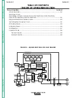
THEORY OF OPERATION
E-5
E-5
SQUARE WAVE TIG 355
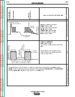
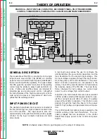
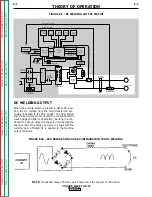
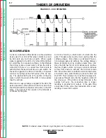
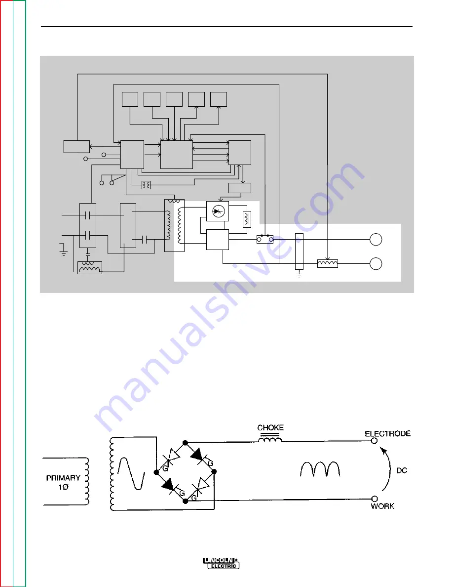
DC WELDING OUTPUT
When the polarity switch is placed in either DC posi-
tion, the AC voltage from the main transformer sec-
ondary is applied to the SCR bridge. The SCR bridge
and choke circuits are connected in a conventional full
wave bridge and filter configuration, resulting in a con-
trolled DC output. Since the choke is in series with the
negative leg of the bridge and also in series with the
welding load, a filtered DC is applied to the machine
output terminals.
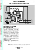
FIGURE E.5 – DC WELDING OUTPUT CIRCUIT
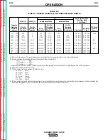
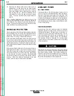
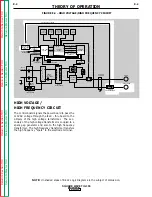
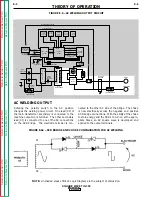
NOTE: Unshaded areas of Block Logic Diagram are the subject of discussion.
HIGH VOLTAGE
TRANSFORMER
CIRCUIT
REMOTE
RECEPTACLE
GAS/WATER
SOLENOIDS
FANS
115VAC
RECEPTACLE
INPUT
CONTACTOR
R
E
C
O
N
N
E
C
T
POWER
FACTOR
CAPACITORS
FEED - THRU
BOARD
CONTROL
BOARD
POWER
BOARD
SNUBBER
BOARD
MAIN
TRANSFORMER
AC
AC
DC-
DC+
POLARITY
SWITCH
SHUNT
C
H
O
K
E
BY-PASS
BOARDS
WORK
ELECTRODE
HI-FREQ
TRANSFORMER
PILOT
TRANSFORMER
START/
STOP
PANEL
SWITCHES
UPPER
CONTROL
PANEL
LOWER
CONTROL
PANEL
DISPLAY
BOARD
STATUS
BOARD
ELECTRODE SENSE
HIGH FREQUENCY SPARK
115VAC
INTERLOCK
HI-FREQ AND GAS/WATER
115VAC -
115VAC
CONTROL TRANSFORMER
INTERLOCK
ELECTRODE
SENSE
REMOTE
COMMANDS
GATE COMMANDS
HI-FREQ/ WATER/GAS
COMMANDS
INTERLOCK
115VAC
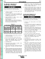
SCR
TRIGGER
15VDC
115VAC
FIGURE E.5a – SCR BRIDGE AND CHOKE CONFIGURATION FOR DC WELDING


