F-35
F-35
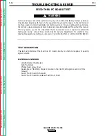
FEED-THRU PC BOARD TEST
(continued
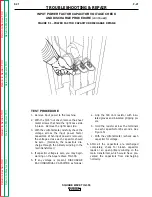
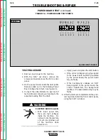
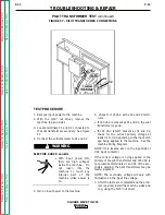
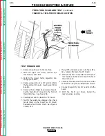
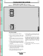
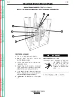
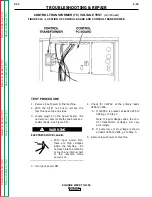
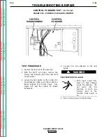
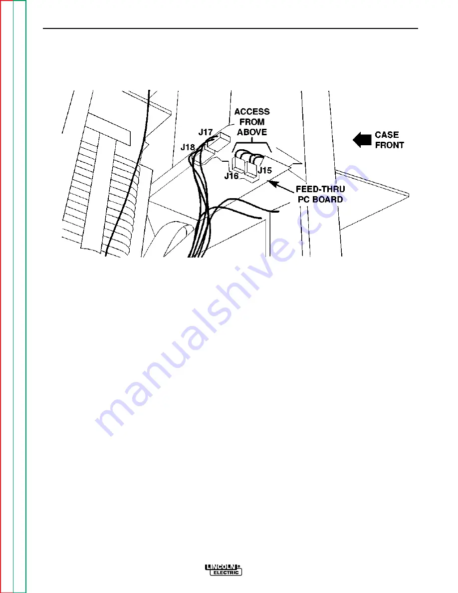
FIGURE F.8 - FEED-THRU PC BOARD LOCATION
TROUBLESHOOTING & REPAIR
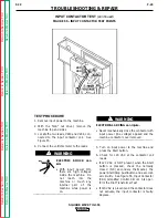
TEST PROCEDURE
1. Remove input power to the machine.
2. With the 5/16" nut driver, remove the
machine top and sides.
3. Perform the power factor capacitor dis-
charge procedure.
4. Remove plugs J15, J16, J17, and J18 from
the feed-thru PC board. See Figure F.8 for
location.
5. Remove the 4 phillips head screws mount-
ing the feed-thru PC board to the floor of
the control box. See Figure F.8.
6. Carefully remove the feed-thru PC board.
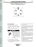
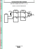
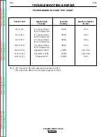
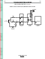
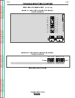
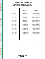
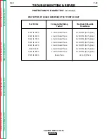
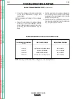
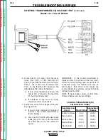
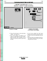
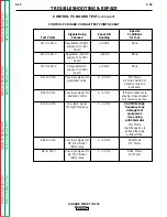
7. Test for the resistances between the check
points listed on the Feed-Thru PC Board
Resistance Test Points Chart. See Figures
F.9 and F.10.
• If any of the resistances are out of specifica-
tion, replace the feed-thru PC board.
8. After the tests are completed and the prob-
lem repaired, install and connect the feed-
thru PC board:
• Carefully mount the board to the floor of the
control box using the 4 phillips head screws.
• Connect plugs J15, J16, J17, and J18 to the
board.
9.
With the 5/16" nut driver, install the
machine sides and top.
SQUARE WAVE TIG 355
Retur
n to Section TOC
Retur
n to Section TOC
Retur
n to Section TOC
Retur
n to Section TOC
Retur
n to Master TOC
Retur
n to Master TOC
Retur
n to Master TOC
Retur
n to Master TOC

