


F-46
F-46
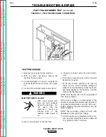
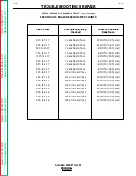
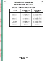
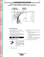
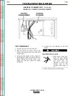
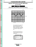
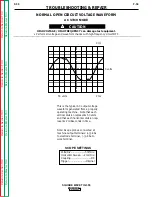
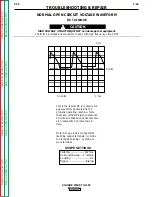
CONTROL TRANSFORMER (T5) VOLTAGE TEST
(continued)
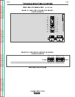
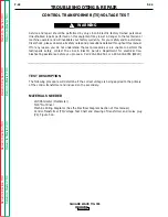
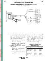
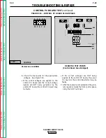
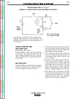
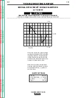
FIGURE F.14 – PLUG P4 DETAILS
TROUBLESHOOTING & REPAIR
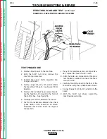
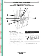
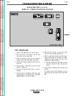
6. Check fuse F1 (0.5 amp). Test the resis-
tance from 6J15, on the feed-thru PC
board, to the #265 lead at the control trans-
former. Also check the resistance from
7J15, on the feed-thru PC board, to the
#266 lead at the control transformer.
A. If zero ohms resistance is shown, the
test is OK. Proceed to the feed-thru
PC board continuity test.
B. If resistance of any value is shown,
check wires and connections.
7. Test for the correct AC voltages at Plug P4.
See Figure F.14.
A. If one or more voltages are missing or
incorrect, the control transformer is
faulty. Replace.
B. Also check for 24VAC at the two black
leads going to 1J16 on the feed-thru
PC board and 1J9 on the control PC
board.
IMPORTANT: If the control transformer is
replaced, refer to the label on the new trans-
former for correct primary lead connections. If
connected wrong, the machine will have no
OCV output. If no OCV occurs, reverse the
control transformer primary connections and
recheck machine OCV.
NOTE: If input voltage varies, control trans-
former voltages will vary accordingly.
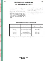
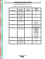
CONTROL TRANSFORMER (T5)
VOLTAGE TEST CHART
Secondary Lead
Approximate
Colors
Plug P4 Pins
Voltages
Yellow to Yellow
1 to 2
10VAC
Blue to Blue
4 to 6
32VAC
White to Blue
5 to 6
16VAC
Red to White
10 to 5
18VAC
Red to Red
10 to 12
36VAC
SQUARE WAVE TIG 355
Retur
n to Section TOC
Retur
n to Section TOC
Retur
n to Section TOC
Retur
n to Section TOC
Retur
n to Master TOC
Retur
n to Master TOC
Retur
n to Master TOC
Retur
n to Master TOC
END VIEW
BLACK
LEADS


