

Retur
n to Section TOC
Retur
n to Section TOC
Retur
n to Section TOC
Retur
n to Section TOC
Retur
n to Master TOC
Retur
n to Master TOC
Retur
n to Master TOC
Retur
n to Master TOC
F-50
F-50
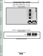
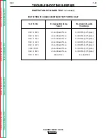
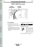
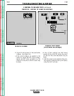
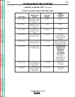
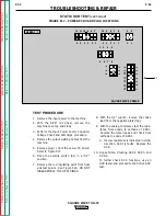
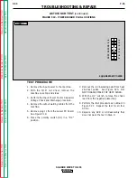
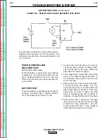
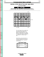
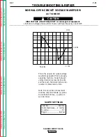
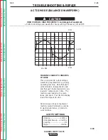
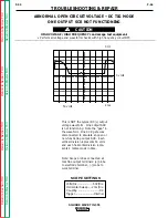
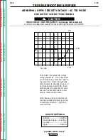
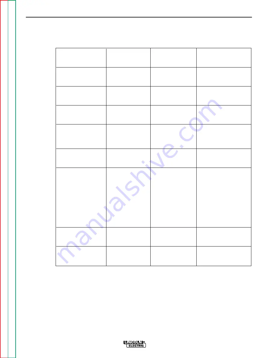
CONTROL PC BOARD TEST
(continued)
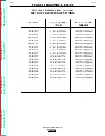
CONTROL PC BOARD VOLTAGE TEST POINTS CHART
TROUBLESHOOTING & REPAIR
SQUARE WAVE TIG 355
Special
Signals Being
Expected
Conditions
Test Points
Checked
Reading
for Test
3J13 to 5J13
Reg15VDC
+15VDC
None
supply to control
board
4J13 to 5J13
Regulated -15VDC
-15VDC
None
supply to control
board
1J13 to 2J13
Unregulated DC
+12VDC
None
supply to control
board
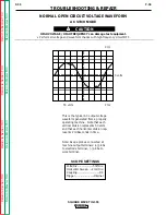
R11 to 5J13
Low logic signal for
0 - 2 VDC
TIG Mode
gas/water valve
Arc Start Switch or
Amptrol must be
activated
R32 to 5J13
Low logic signal for
0 - 2 VDC
If input contactor is
interlock control
staying closed signal
will normally be low.
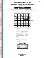
R13 to 5J13
Low logic signal
0 - 2 VDC
CAUTION: High
for high frequency
frequency may
damage test
equipment.
Use analog
volt/ohmmeter
TIG Mode
High frequency is
active after gas
preflow time.
R66 to 5J13
Low logic signal for
0 - 2 VDC
StickMode
DC OCV Boost
DC Mode
(CR3) relay
R8 to 5J13
Low logic signal for
0 - 2 VDC
Stick Mode
AC OCV Boost
AC Mode
(CR2) relay


