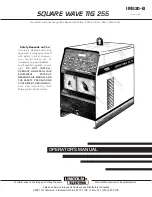
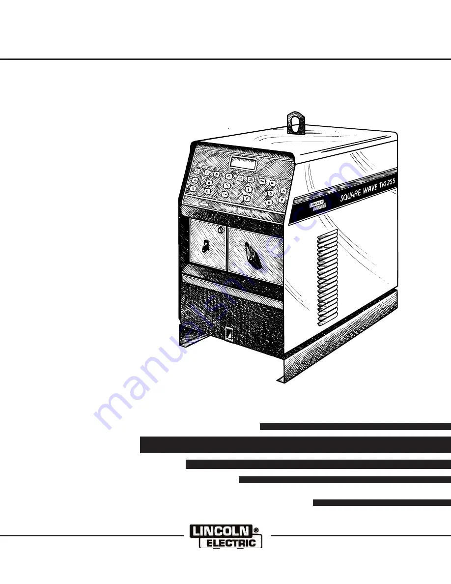
background image

SQUARE WAVE TIG 255

OPERATOR’S MANUAL

Sales and Service through Subsidiaries and Distributors Worldwide

22801 St. Clair Ave. Cleveland, Ohio 44117-1199 U.S.A. Tel. (216) 481-8100

World's Leader in Welding and Cutting Products

Premier Manufacturer of Industrial Motors

IM520-B

January, 1997

Safety Depends on You

Lincoln arc welding and cutting
equipment is designed and built
with safety in mind. However,
your overall safety can be
increased by proper installation ...
and thoughtful operation on your
part.

DO

NOT

INSTALL,

OPERATE OR REPAIR THIS
EQUIPMENT

WITHOUT

READING THIS MANUAL AND
THE SAFETY PRECAUTIONS
CONTAINED THROUGHOUT.

And, most importantly, think
before you act and be careful.

For use with machines having Code Number 10022 thru 10026 & 10134, 10451,10452,10453.

Summary of Contents for SQUARE WAVE TIG 255

Page 1: ...1997 Safety Depends on You Lincoln arc welding and cutting equipment is designed and built with safety in mind However your overall safety can be increased by proper installation and thoughtful operation on your part DO NOT INSTALL OPERATE OR REPAIR THIS EQUIPMENT WITHOUT READING THIS MANUAL AND THE SAFETY PRECAUTIONS CONTAINED THROUGHOUT And most importantly think before you act and be careful Fo...

Page 2: ...afety information it is strongly recommended that you purchase a copy of Safety in Welding Cutting ANSI Standard Z49 1 from the American Welding Society P O Box 351040 Miami Florida 33135 or CSA Standard W117 2 1974 A Free copy of Arc Welding Safety booklet E205 is available from the Lincoln Electric Company 22801 St Clair Avenue Cleveland Ohio 44117 1199 BE SURE THAT ALL INSTALLATION OPERATION MA...

Page 3: ...cal earth ground 3 f Maintain the electrode holder work clamp welding cable and welding machine in good safe operating condition Replace damaged insulation 3 g Never dip the electrode in water for cooling 3 h Never simultaneously touch electrically hot parts of electrode holders connected to two welders because voltage between the two can be the total of the open circuit voltage of both welders 3 ...

Page 4: ...ent the welding sparks from starting a fire Remember that welding sparks and hot materials from welding can easily go through small cracks and openings to adjacent areas Avoid welding near hydraulic lines Have a fire extinguisher readily available 6 b Where compressed gases are to be used at the job site special precautions should be used to prevent hazardous situations Refer to Safety in Welding ...

Page 5: ... et non inflammables 4 Des gouttes de laitier en fusion sont émises de l arc de soudage Se protéger avec des vêtements de protection libres de l huile tels que les gants en cuir chemise épaisse pantalons sans revers et chaussures montantes 5 Toujours porter des lunettes de sécurité dans la zone de soudage Utiliser des lunettes avec écrans lateraux dans les zones où l on pique le laitier 6 Eloigner...

Page 6: ...re the information must be followed to avoid minor personal injury or damage to this equipment CAUTION Please Examine Carton and Equipment For Damage Immediately When this equipment is shipped title passes to the purchaser upon receipt by the carrier Consequently Claims for material damaged in shipment must be made by the purchaser against the transportation company at the time the shipment is rec...

Page 7: ... Limitations 17 Controls and Settings 18 Hand and Foot Amptrol Operation 20 Welding Operation 20 23 Tig Welding Guidelines 20 Tig Welding Sequence of Operation 2 Step Mode 21 Tig Welding Sequence of Operation 4 Step Mode 22 Advanced Tig Welding Features 22 Stick Welding 23 Auxillary Power 23 Overload Protection 23 Accessories 24 Maintenance 25 26 Safety Precautions 25 Routine and Periodic Maintena...

Page 8: ...ED INPUT WIRE AND FUSE SIZES Input Voltage Frequency 208 60 230 60 460 60 575 60 200 50 60 220 50 60 380 50 60 400 50 60 415 50 60 440 50 60 500 50 60 Input Ampere Rating on Nameplate 81 74 37 30 85 77 46 43 41 39 34 Type 75 C Copper Ground Wire in Conduit AWG IEC Sizes 6 16mm2 8 10mm2 10 6mm2 10 6mm2 6 16mm2 8 10mm2 8 10mm2 10 6mm2 10 6mm2 10 6mm2 10 6mm2 Fuse Super Lag or Breaker Size 125 100 50...

Page 9: ...nd national electrical codes for proper grounding methods The spark gap oscillator in the high frequency generator being similar to a radio transmitter can be blamed for many radio TV and electronic equipment interference problems These problems may be the result of radiated interference Proper grounding methods can reduce or eliminate radiated interference Radiated interference can develop in the...

Page 10: ...problems and result in unsatisfactory welding performance resulting from lost high frequency power See Figure 1 for the location of the rating plate the entry hole and the reconnect panel FIGURE 1 REAR PANEL 1 RATING PLATE 3 220V RECEPTACLE BREAKER 2 INPUT ENTRY 50 60 HZ MACHINE ONLY RECONNECT PANEL 4 115V RECEPTACLE BREAKER Have a qualified electrician connect the input leads to L1 and L2 of the ...

Page 11: ...permanently wired into the power system No plugs or connectors are necessary 1Also called inverse time or thermal magnetic circuit breakers circuit breakers which have a delay in tripping action that decreases as the magnitude of the current increases FIGURE 2 FRONT PANEL 1 CONTROL AND DISPLAY AREA 5 OPTIONAL WATER SOLENOID 2 POWER SWITCH 6 GAS SOLENOID 3 THERMOSTATIC 7 WORK LEFT AND PROTECTION LI...

Page 12: ...ructions for the water cooler or TIG torch being used STICK ELECTRODE CABLE CONNECTION Turn the Power switch Off Run the electrode and work cables through the strain relief holes below the welding output terminals and connect the cables to the proper terminals This strain relief prevents damage to the welding output terminals if the cables are pulled excessively Select cable size according to Tabl...

Page 13: ...our head out of fumes Use ventilation or exhaust to remove fumes from breathing zone WELDING SPARKS can cause fire or explosion Keep flammable material away Do not weld on containers that have held combustibles ARC RAYS can burn Wear eye ear and body protection OPERATION OPERATING INSTRUCTIONS General Warnings SAFETY INSTRUCTIONS Observe additional Safety Guidelines detailed in the beginning of th...

Page 14: ...CURRENT CONTROL INCREASE OUTPUT DECREASE HIGH FREQUENCY CONTINUOUS HIGH FREQUENCY START ONLY HIGH FREQUENCY OFF CLEAN INCREASE POSITIVE POLARITY PENETRATE INCREASE NEGATIVE POLARITY TIG PULSER AFTERFLOW AFTERFLOW TIME GRAPHIC SYMBOLS THAT APPEAR ON THIS MACHINE OR IN THIS MANUAL OPERATION HF ...

Page 15: ...NT OUTPUT WATER COOLANT INPUT WORK CONNECTION GAS OUTPUT GAS INPUT ELECTRODE CONNECTION PROTECTIVE GROUND SINGLE PHASE TRANSFORMER AC DC RECTIFIER POWER SOURCE TIG GTAW SINGLE PHASE PULSED PER SECOND GRAPHIC SYMBOLS THAT APPEAR ON THIS MACHINE OR IN THIS MANUAL CONT AC POLARITY OPERATION f AC WAVE BALANCE ...

Page 16: ...485 mm x 760 mm footprint GENERAL DESCRIPTION The Square Wave TIG 255 is a constant current single range square wave AC DC TIG GTAW arc welding power source with built in high frequency stabilization It also has stick SMAW capability It is available from the factory in one model only there are no factory installed options only variations in input voltage and frequency The Square Wave TIG 255 inclu...

Page 17: ...gs Large safety margins and protective circuits protect rectifiers from transient voltages and high currents Submersion dipping of assembled transformer choke rectifier in special sealing insulating material gives added protection against moisture and corrosive atmospheres Line Voltage Compensated Thermostatically Protected Electronic Over Current Protection Hinged Cover over Output Panel Limitati...

Page 18: ...heck the settings of the up down keys 1 WELD MODE KEYS These keys select the Weld Mode desired TIG 2 Step TIG 4 Step or Stick Read the complete Operating Instructions section for more information on TIG 2 Step and TIG 4 Step 2 CURRENT CONTROL This area contains the Local Remote keys as well as the Amps Up Amps Down keys These keys are used to set the welding current from 5 to 315 amps as well as t...

Page 19: ... OVER TEMPERATURE LIGHT A yellow light which only lights when an over temperature situation occurs See the Maintenance Section for more information on the thermostatic protection 3 POLARITY SWITCH Selects DC AC or DC welding polarity Do not switch under load 7 CONTROL PANEL The display is divided into five sections See Figures 4A and 4B FIGURE 4A DISPLAY A AC DC INDICATOR D MOMENTARY DISPLAY B VOL...

Page 20: ...an also be used as arc start switches if Local Current Control is selected For simplicity the following explanation will refer only to Amptrols meaning both Foot and Hand models The term minimum refers to a Foot pedal in the up position as it would be with no foot pressure or a Hand Amptrol in the relaxed position with no thumb pressure Maximum refers to a fully depressed Foot Amptrol or a fully e...

Page 21: ...le 2 010 25 0 020 50 0 040 1 0 1 16 1 6 3 32 2 4 1 8 3 2 5 32 4 0 3 16 4 8 1 4 6 4 2 15 5 20 15 80 70 150 150 250 250 400 400 500 500 750 750 1000 3 3 3 10 20 15 30 25 40 40 55 55 80 80 125 2 15 5 15 10 60 50 100 100 160 150 210 200 275 250 350 325 450 2 15 5 20 15 80 70 150 140 235 225 325 300 400 400 500 500 630 2 15 10 20 20 30 30 80 60 130 100 180 100 240 190 300 250 400 5 20 20 60 60 120 100 ...

Page 22: ...atch start welding 6 Select AC or DC electrode polarity See Table 2 7 If welding with AC polarity select Auto Balance This gives the optimum ratio between cleaning and penetration automatically adjusted for the output current If manual adjustment of the AC Wave Balance is desired select Manual Balance and adjust the wave balance with the Cleaning and Penetration keys See the Advanced Features sect...

Page 23: ...und current is fixed at 50 STICK WELDING 1 Remove the amptrol or Arc Start Switch from the Remote Receptacle 2 Turn the welder on The Control Panel Display and red LEDS will illuminate when the power is on 3 Select Stick Mode and Local Current Control Set the output current using the Amps Up Down keys The output current setting will be displayed on the Ammeter No other functions or adjustments ope...

Page 24: ...the undercarriage attached The undercarriage is designed for hand moving only mechanized towing can lead to injury and or damage to the Square Wave TIG 255 INSTALLATION OF FIELD INSTALLED OPTIONS Instructions for connecting the K932 1 Undercarriage and the K559 2 Magnum Cooler Horizontal TIG Mounting Bracket are included with those accessories Installation of the K963 Hand Amptrol the K814 Arc Sta...

Page 25: ...ansformer Output Studs Polarity Switch Rectifier Assembly Control Box Assembly Spark Gap Assembly Protection PC Board Mounted to rear of control box assembly 3 Inspect welder output and control cables for fraying cuts and bare spots 4 Keep TIG torch and cables in good condition 5 The fan motor has sealed ball bearings which require no maintenance 6 Inspect spark gap spacing at regular intervals to...

Page 26: ...2 6 4 28 3 2 FIGURE 6 GENERAL ASSEMBLY EXPLODED VIEW 1 MAIN TRANSFORMER 5 CONTROL BOX ASSEMBLY 2 OUTPUT STUDS 6 SPARK GAP ASSEMBLY 3 POLARITY SWITCH 7 PROTECTION PC BOARD 4 RECTIFIER ASSEMBLY Mounted to rear of control box assembly ...

Page 27: ...EM SYMPTOM Look under the column labeled PROBLEM SYMPTOMS This column describes possible symptoms that your machine may exhibit Find the listing that best describes the symptom that your machine is exhibiting Step 2 PERFORM EXTERNAL RECOMMENDED TESTS The second column labeled POSSIBLE AREAS OF MISADJUSTMENT S lists the obvious external possibilities that may contribute to the machine symptom Perfo...

Page 28: ...eck the input voltage at the machine Input voltage must match the rating plate and reconnect the panel 3 Blown or missing fuses in input line 1 Check for proper input voltages As per nameplate and reconnect panel 1 Inspect to assure that the arc start switch is in the on closed position when welding in the TIG Mode 1 Machine MUST be in one of the TIG Modes 2 The arc start switch or amptrol may be ...

Page 29: ...ceed recommended duty cycle 2 Dirt and dust may have clogged the cooling channels inside the machine Blow out unit with clean dry compressed air 3 Air intake and exhaust louvers may be blocked due to inadequate clearance around machine 1 Inspect output stud insulators for cracks or signs of over heating RECOMMENDED COURSE OF ACTION If all recommended possible areas of misadjustment have been check...

Page 30: ... overheated condition Thermal overload 1 Be sure that the proper weld mode is selected For example the high frequency keys and keypad lights LEDS are not active in the stick mode 1 Background noise may be too loud for user to hear beeper RECOMMENDED COURSE OF ACTION If all recommended possible areas of misadjustment have been checked and the problem persists Contact your local Lincoln Authorized F...

Page 31: ...ctrode may be too large in diameter 2 Tungsten not Sharp when welding in DC negative mode 3 If helium is used as a shielding gas then reduce the percentage of helium 4 Adjust flow rate of shielding gas 5 Check hoses and connections for leaks 1 Manual balance control set improperly set to negative 10 10 for maximum penetration 1 Tungsten electrode may be contaminated Replace or sharpen 2 Shielding ...

Page 32: ... as Lincoln Stable Arc Cable Cables should be as short as possible 1 The arc start switch or amptrol may be defective There should not be any continuity between pins D and E on the arc start cable connector unless the unit is actuated 2 If an amptrol is not being used the machine must be in the Local Control Mode 1 Torch may be faulty 2 If an amptrol is not being used then the machine must be in t...

Page 33: ...shorted Check gap as per maintenance instructions 1 Gas supply is empty or not turned on 2 Gas or water hose may be pinched 3 Gas or water solenoid may be blocked with dirt Use filters to prevent reoccurrence Consult your Local welder gas distributor 1 Tungsten electrode may be too small for process 2 Manual balance control may be misadjusted Readjust to the negative direction 3 If helium gas is b...

Page 34: ...emote Control Mode the remote amptrol may be defective or not installed properly 2 If the output is low when the machine is in the Local Control Mode the problem could be internal to the machine 1 Check work and electrode cables for loose or poor connections 2 The weld cables may be too small or too long to permit the desired current to flow 3 The preset current adjustment may be set too low RECOM...

Page 35: ... 0 E 2 3 6 2 3 5 2 3 2 B 2 2 9 A 2 3 9 A 2 3 9 2 3 5 A 2 3 8 A R 3 R 4 5 2 A 4 19 96D G2719 WIRING DIAGRAM SQUARE WAVE TIG 255 CODE 10022 10023 10024 NOTE This diagram is for reference only It may not be accurate for all machines covered by this manual The specific diagram for a particular code is pasted inside the machine on one of the enclosure panels If the diagram is illegible write to the Ser...

Page 36: ...A 239A 239 235A 238A R3 R4 1 24 97H G3302 WIRING DIAGRAM SQUARE WAVE TIG 255 CODE 10451 10452 10453 52 50 232 NOTE This diagram is for reference only It may not be accurate for all machines covered by this manual The specific diagram for a particular code is pasted inside the machine on one of the enclosure panels If the diagram is illegible write to the Service Department for a replacement Give t...

Page 37: ...lletin ED 80 or call 216 383 2259 and ask for the Welding School Registrar Lincoln Welding School BASIC COURSE 700 00 5 weeks of fundamentals There is a 10 discount on all orders of 50 00 or more for shipment at one time to one location Orders of 50 or less before discount or orders outside of North America must be prepaid with charge check or money order in U S Funds Only Prices include shipment ...

Page 38: ...h electrically live parts or electrode with skin or wet clothing Insulate yourself from work and ground No toque las partes o los electrodos bajo carga con la piel o ropa mojada Aislese del trabajo y de la tierra Ne laissez ni la peau ni des vêtements mouillés entrer en contact avec des pièces sous tension Isolez vous du travail et de la terre Berühren Sie keine stromführenden Teile oder Elektrode...

Page 39: ... gute Be und Entlüftung des Arbeitsplatzes Mantenha seu rosto da fumaça Use ventilação e exhaustão para remover fumo da zona respiratória Turn power off before servicing Desconectar el cable de alimentación de poder de la máquina antes de iniciar cualquier servicio Débranchez le courant avant l entretien Strom vor Wartungsarbeiten abschalten Netzstrom völlig öffnen Maschine anhalten Não opere com ...

Page 40: ...t covered by this warranty One Year Equipment not listed above such as gun and cable assemblies water coolers FAS TRAK or MIG TRAK equipment Power Arc 4000 generator welders Wire Feed Module Factory Installed and field installed optional equipment TO OBTAIN WARRANTY COVERAGE You are required to notify Lincoln Electric your Lincoln Distributor Lincoln Service Center or Field Service Shop of any def...

Reviews: